Acid-gas injection in New Mexico relieves sulfur-recovery unit duty
The original acid-gas injection project near DCP Midstream’s Artesia, NM, gas plant started up in November 2003 and consisted of drilling an injection well and installing an acid-gas injection compressor. The project’s initial aim was to eliminate use of the plant’s sulfur-recovery unit to reduce operating costs, improve safety, and enhance environmental performance.
The injection horizon is the Devonian formation at 11,500 ft. The compressor is a six-stage, electric-motor-driven, reciprocating unit. The acid-gas design volume is 1.5 MMscfd of water-saturated gas at 2-8 psig suction pressures and up to 2,000-psig discharge pressure. The design composition of the acid gas includes an H2S content of 33-45 mole %. The balance of the acid gas is CO2 with typically about 1% hydrocarbon. The project shutting down envisioned the existing three-bed Claus sulfur-recovery unit.
Design, development
This design is a reconfiguration of the unit to allow injection pressure to be increased to 2,750 psig from 2,000. This increase was needed to overcome the low permeability of the formation to meet expected long-term injection rates. A custom cylinder design was required. The reconfigured design started up in December 2006.
The project was developed with best practices from DCP Midstream, its predecessor companies,1 and previous industry projects. Some general guidelines from the other AGI sites were to inject below the deepest producing formation and into a formation with a minimum number of existing well-bore penetrations.
All previous DCP Midstream sites were located as close to the amine system as allowable within plant-equipment spacing guidelines, typically directly on the plant site to minimize hazards associated with the H2S inventory in piping and equipment and to avoid transportation issues offsite.
Other major process decisions made from previous company and industry2-4 experience were partial use of stainless steel in the cold or “wet” portions of the compression equipment including the first-stage suction for a consistent design philosophy for all stages. Another decision was to rely on the water-saturation characteristics of the acid gas at compression and injection conditions partially to dehydrate the acid gas and consequently to use carbon steel (sour service) metallurgy for the hot-discharge lines and injection well. Alloy trim is included in the wellhead and downhole valves. A final decision from previous company projects was to install subsurface safety valves and bottomhole check valves for safety reasons.
Geological evaluation
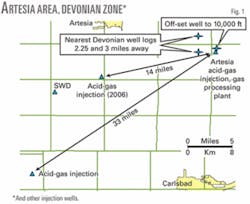
A geological evaluation identified several potential formations in the Artesia plant area in Eddy County, NM. The deepest production in the immediate area is from the Morrow zone at about 10,000 ft. Drilled to this formation was a gas production well adjacent to the plant as well as two wells 2-3 miles west of the plant into deeper zones with complete well log information. Log cross-sections were prepared from available information and correlated to the plant site with the off-set well.
Based on this information, DCP Midstream selected the Devonian formation as the injection target because it appeared to meet the selection criteria: to provide good injection capability via naturally occurring fractures and to be below other production, thereby having a minimum number of wellbore penetrations especially at the preferred location near the plant.

Devonian is a water-saturated limestone-dolomite (carbonate) typically not productive in the area. Drill stem tests of Devonian in nearby wells showed high rates of water production.
In addition, another operator was already injecting acid gas and water into the formation in Eddy County, although 33 miles away. Subsequently in 2006 a third operator initiated injection into this formation 14 miles away and also began operating a saltwater disposal well (SWD) in this formation.
Design
Fig. 2, a pressure-temperature plot for the low H2S design case, shows the compressor process design and the phase envelope, hydrate curve, and compressor operating conditions. As shown there, high inter-stage temperatures were required for this air-cooled unit at peak summer conditions. The final scrubber temperature of 140° F. became a requirement for a six-stage design since it provided extra margin above the acid-gas dewpoint temperature.
This fifth-stage inter-cooler temperature is the most critical and is used for both louver and fan speed control of the air cooler. The hydrate temperature is about 80° F. for the higher stages, which is of concern during winter operation and at turndown conditions.
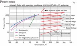
Fig. 2 shows the increase in pressure from 5 psig to 2,000 psig in the six-stage compressor. The pressure then increases from 2,000 psig to 5,800 psig (including the 10% over-prediction of density by the simulation program) as the fluid flows down the well. The heat of compression also increases the temperature in the tubing.
The six-stage compressor unit was designed to meet sour-service requirements.5 A JGJ-6 Ariel compressor frame was selected because of its rod load and cylinder size. The unit includes long two-compartment distance pieces, purged distances pieces, purged primary and secondary packing, and other design details typical for acid-gas injection.
One modification for this unit was the use of nylon material for the valve plates on the low-stage suction valves and high-temperature nylon for the remaining valves. This material is suitable for temperatures up to 340° F. and has performed well. Previous acid-gas injection units have used steel valve plates, either carbon steel or stainless steel, or other thermoplastic materials such as PEEK (polyetheretherkeytones).1 2 6
Table 1 summarizes the design parameters for the unit as originally configured (with parameters for the reconfigured unit, 2006 design shown in parenthesis).

The driver is a 4,160 v, 600-hp motor with a variable-speed drive. The VFD’s speed range was 900-1,400 rpm for the original design. The cooler is a common unit for all six stages.
The very high discharge pressure-well above critical-will cause the gas to cool significantly to about -110° F. when expanded from 2,000 psig and 130° F. to close to atmospheric pressure. Therefore, the compressor recycle valve originates upstream of the aftercooler for operation on acid gas. All relief valves are directed to the plant’s acid-gas flare.
It cannot be emphasized enough that for dense-phase acid gas, cryogenic temperatures are possible during depressurization, compounding the hazards associated with this toxic gas. On this project a methanol-injection pump was added after start-up to displace the dense-phase acid gas from all lines before depressurization.
Initial fracture stimulation
The well was perforated at 11,207-11,260 ft and 11,326-11,412 ft. Drillstem testing completed on each section revealed only small amounts of water production from the Devonian formation, indicating much lower permeability than expected. Openhole logs were also completed and sidewall cores collected and analyzed in a laboratory. All of this information confirmed the low permeability of the formation.
DCP Midstream then decided to complete the well and enhance permeability using stimulation techniques. This work improved the expected well performance and was designed for a fracture half-length of 173 ft with 45,000 gal of 15% hydrochloric acid.
Water injection tests unfortunately revealed the predicted performance was still marginal for the compressor capability of 2,000 psig. Based on these test results, the injection permit was amended for injection of acid gas at pressures up to 3,240 psig. It appeared that the initial performance should be satisfactory, but if the performance deteriorated, design acid-gas injection rates would not be met.
The well could perform better than expected as several sites have documented decreases in injection pressure with time possibly due to the action of the acid gas in dissolving or etching the carbonate rock formation in the presence of formation water.3 7 Laboratory tests have shown that increased permeability is possible with time8 as well as decreased permeability for various rocks.
Operation with acid gas would also allow collection of data to evaluate reservoir performance and to determine the best corrective option if performance were poor. Due to the possible need for a higher pressure cylinder a forged billet of 17-4PH stainless steel for the custom cylinder was placed on order to expedite a modification if required and the original compressor was installed.
Operation-constant rate
Operation on acid gas began on Nov. 17, 2003, initially at a constant acid-gas rate of about 1 MMscfd. The pressure rose rapidly toward the maximum operating pressure of 2,000 psig within a few weeks.
Fig. 3 shows initial well performance; the data are hourly average values. The H2S concentration in the acid gas is calculated from the gas analyzer readings measured for H2S and CO2 concentrations in the inlet gas to the amine system, which typically removes all of the acid gas from the inlet gas. There is also correlation to a logarithmic pressure increase. This is analogous to a gas storage field, which will often display a logarithmic pressure vs. time relationship.
Fig. 3 also shows a number of interesting operational issues. When the well is shut-in for short periods the pressure declines slowly as the acid gas leaks off into the low-permeability formation. A slight impact of temperature appears in Fig. 3 as a gradual increase in pressure above the trend is seen when the temperature increases and a gradual return to the trend when the temperature decreases.
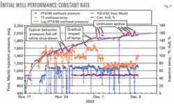
Finally, Fig. 3 also shows some “unknown spikes” in pressure that occurred very rapidly. During cold weather operation on a rich gas stream, the plant was experiencing foaming in the amine system that caused hydrocarbon entrainment in the amine, increased hydrocarbon content in the acid gas, and a subsequent increase in injection pressure.
A 1% incremental increase in hydrocarbon content will cause a 60-psig rise in injection pressure due the impact of the relatively “non-condensable” hydrocarbon on the acid-gas density. This effect has definitely been seen in acid-gas injection performance.
Second fracture stimulation
The larger, follow-up acid fracture stimulation was through the production tubing using 42,000 gal of 28% hydrochloric acid, viscoelastic diverting acid, and was followed by a large post-flush step with twice this amount of water. The use of this acid and the water post-flush was to allow dispersal of any dissolved solid to the end of the fracture so that the well would not need to be flowed back.
Following the stimulation, the well was unable to accept flow because the surface shut-in pressure increased to greater than 2,100 psig, greater than the compressor shut-down pressure. One explanation is that the injection of acid gas had gradually established gas permeability in the reservoir and the large amount of liquid (hydrochloric acid and water) injected in the reservoir blocked the flow by isolating the gas pockets, in effect re-establishing permeability to water and decreasing permeability to gas.
The sulfur-recovery unit (SRU) was restarted in March 2004 to handle the acid-gas volume and avoid flaring. A follow-up workover to inject a combination of CO2 and methanol to enhance mutual solubility of the reservoir phases and re-establish permeability to acid gas was completed. Some of the workover fluid was also flowed back and recovered, which required safety precautions for sour gas since some acid gas was entrained.
The combination of these actions returned the wellhead pressure to a typical shut-in value of less than 1,100 psig. Injection was then restarted in July 2004 in parallel with operation of the SRU.
Long-term performance
Fig. 4 shows the long-term performance for the Artesia acid-gas injection system covering nearly 4 years. Flows and H2S concentration are daily average values and pressure and temperature are single point-in-time values each morning. The data in Fig. 4 first repeat the early data that were shown in Fig. 3 with the rapid initial increase in pressure followed by constant pressure injection for a few months with a declining injection rate. The shut-in pressure during the well was greater than 2,000 psig and a slow decline as the pressure leaked into the formation. The rapid drop in pressure to 1,100 psig from 1,800 psig occurred at the end of May 2004 due to the last workover injecting CO2 and methanol and then recovering some of the injected fluid.
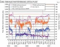
Fig. 4 then covers the operating data from restarting injection in July 2004 through August 2007. Injection temperature has been fairly constant at about 90° F., although precise control is limited due to the common cooler. The composition of the acid gas has gradually trended downward with the H2S decreasing steadily to about 30% from 40% as the mix of inlet gas to the plant changed.
The data in Fig. 4 also show the relationship between injection pressure and injection rate. Following restart of injection in July 2004, the well was operated in parallel with the SRU at injection rates of about 400 Mscfd. The pressure is generally flat at this low injection rate, at about 1,500 psig. There are also periods when the well is shut-in, the wellhead pressure drops to 1,200 psig, and the SRU takes the full volume.
Finally, there are periods when the SRU is shut-down for maintenance and the well handles the full volume of 700-1,000 Mscfd and the pressure increases to 1,800 psig or higher. The rate (slope) of this increase in pressure has decreased as the well continues to clean up with time. The system has been successfully injecting the entire volume of acid gas since April 2006 allowing shutdown of the SRU.
Reservoir model
The performance data through December 2005 and well data were used to prepare a single-well radial model for the reservoir. The model has 16 vertical layers of varying permeability using data from the sidewall cores adjusted to match the drillstem tests. One 3-ft high layer has a permeability to air of 32 md indicating a natural fracture. A second layer has 1.5 md, and the rest of the zone has low permeability with a height-weighted average of 0.56 md for the unadjusted core data.
The porosity ranges from 3% to 17% with a weighted average of 6%. These values compare unfavorably to average permeability of 40 md and average porosity of 10% reported for 225 Permian basin reservoirs.9
The model also divided the reservoir into six quadrants in a circle and 50 radial rings spaced logarithmically to an outer boundary radius of 10,560 ft (2 miles). The model was tuned by adjusting relative gas permeability and skin factor to match operating data for injection pressure vs. injection rate.
A key assumption in the model is that the high permeability layer is continuous to the model boundary. Performance to date does not suggest a smaller boundary distance for either.10 The history-match results for the model show continued improvement of well performance with time.
A convenient way to show the results is equivalent fracture length, which is calculated from the skin factor. Table 2 shows the improvement in equivalent fracture length with time.
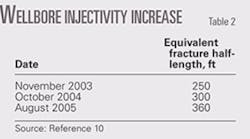
The design-etched length predicted for the initial fracture stimulation was 173 ft; for the second stimulation, 396 ft. The model performance for the initial data for November 2003 through March 2004 had a fracture length of 250 ft to match well performance, which was greater than the design value for the initial stimulation of 173 ft. The performance immediately following the second fracture (July 2004 data not shown in the table) was best matched by assuming that the two highest permeability layers were blocked, which supported the water-blockage theory.
The performance in October 2004 through December 2005 indicated that all layers had reopened and that the effective fracture length was increasing (Table 2) and is still cleaning up and increasing toward the design fracture length of 396 ft from the second stimulation.
Once the history-match cases were finished, a series of prediction cases were completed for 2,000 psig, 2,500 psig, and 3,240 psig injection pressures. These cases corresponded to continued injection with the original six-stage unit, a reconfiguration of the six-stage unit with a custom cylinder, and addition of a separate seven-stage unit.
Based on these simulations the seven-stage options with 3,240-psig discharge pressure could sustain full injection rates for the longest time. The improvement provided at the intermediate pressure, however, provided a sufficient increase in injection-vs.-time behavior to meet commercial plans for the plant at about 40% of the cost of the seventh stage. In addition, use of a single compressor unit instead of two units in series will provide the greatest injection efficiency.
Modification of the sixth-stage cylinder was selected as the best overall commercial and technical choice and allowed use of the previously purchased compressor forging.
Reconfiguration project
The sixth-stage reconfiguration project was authorized, and the original compressor vendor modified the unit. As the design was finalized for the new custom 2.375-in. bore cylinder, it was found that the maximum allowable working pressure could be increased to 3,000 psig for the new cylinder, which allows operation at discharge pressures up to 2,750 psig.
In addition, since the new cylinder is now double acting, it was possible to increase the turndown to 600 rpm without rod-reversal problems. This provides an increased operating range from 0.5 to 1.5. The reconfiguration was also designed for a range of 20-40% H2S using actual extended-analysis results for the hydrocarbon portion of the gas.
The percent of rod reversal is now the lowest on the fifth stage but is well within acceptable limits. If rod-reversal damage occurred, however, it could result in extended downtime for the unit. Therefore, individual thermocouples were provided on the new sixth-stage cylinder and the existing fifth-stage cylinder at both of the discharge valves (head end and crank end). This allows the unit to be shut down immediately if a temperature difference develops between the discharge valves to minimize the chance of catastrophe. Typical high-temperature shutdowns were also retained.
The sixth-stage cylinder packing cases must be cooled due to pressure greater than 2,000 psig. The sixth-stage suction scrubber, suction bottle, discharge bottle, and aftercooler tube section were replaced for the higher pressure requirement. The fifth-stage discharge bottle was re-rated and the fifth-stage intercooler tube section was replaced. The fifth-stage cylinder is rated at 2,200 psig MAWP and did not need to be replaced.
Leaking plug threads had been encountered on the high-pressure air cooler headers with the 304L SS plugs in the original installation possibly due to differential expansion. Therefore, 316L plugs were used in the 316L SS headers of the new cooler sections with a special lubricant/polymer (molybdenum disulfide/PTFE - polytetrafloroethylene) coating to prevent galling.
Installation was completed during a 5-day shutdown of the injection unit. The plant was shut down during this time and gas routed to other plants on the gathering system or shut-in. This nearly eliminated flaring of the acid gas during this time. The unit was run on fuel gas to modify the variable-frequency drive for lower speeds and to check for leaks.
The unit was then started up and put into operation. Even though the plant has operated at maximum inlet-gas capacity, the acid-gas rates are currently about 700-850 Mscfd. The injection pressure had fallen to about 1,600 psig during the shutdown and has only increased to about 1,900 psig by August 2007.
The plant has seen one amine or other plant upset during this time in which the injection pressure climbed rapidly to 2,100 psig. The compressor was able to stay online through this event with the new cylinder configuration.
The new design has allowed the plant to sustain injection at higher rates for short periods of time and even at elevated summer injection temperatures and provides for the expected injection rates for the life of the facility.
Efficiency; CO2 sequestration
The plant has experienced good control efficiency during the 3 years of injection operation.
The cumulative efficiency has been 98.5% from start-up to mid August 2007 and 99.2% for the last 3 years of operation (August 2004 to August 2007). Operation of acid-gas injection in parallel with the sulfur-recovery unit has also improved SRU efficiency by about 2%, primarily due to base-loading the SRU.
The plant has sequestered about 25,620 tons of CO2 by mid August 2007. The current CO2 sequestration rate is 11,000 tons/year. These figures exclude any CO2e emissions related to the generation of power by the utility company used to power the injection compressor.
Operating issues
The plant has experienced a few operating issues during 3 years of operation. The main ones are excessive inter-stage liquids, hydrates, and corrosion. These are compounded by turndown issues.
Inter-stage liquids
Much more liquids than expected have been found in the inter-stage scrubbers. They were designed for a limited amount of water dropout. Extended analyses of the acid gas were collected during injection.
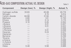
Table 3 compares the actual composition to the design compositions in Table 3. There is less methane than was measured in the previous samples (45% design high case) most likely due to installation of a new amine flash tank. The C2-C5 composition is similar to the older analyses. The C6+ portion showed that the heavy hydrocarbons were primarily aromatic components benzene, toluene, ethylbenzene, and xylenes (BTEX).
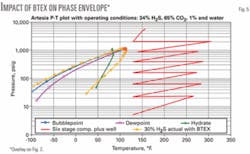
Fig. 5 shows the impact of BTEX on operation. While the critical point and the bubble point curve are not changed much, the dewpoint curve for the phase envelope with the actual composition is shifted to much warmer temperatures.
Hydrates
During winter operations and especially during turndown when excess intercooler area is available, the intercoolers can run colder than design. This is predicted to cause condensation of an acid-gas/BTEX hydrocarbon liquid phase in the scrubbers.
When this liquid is expanded to lower pressure, the fluid can auto-cool, reach hydrate temperature, and plug the liquid line. This effect can be demonstrated with process-simulation calculations and is the cause of level control and freezing problems.
The electrical heat trace was also found to be insufficient, and steam trace was added to provide more heat input and address areas lacking heat trace.
Corrosion rates
After 3 years of operation, ultrasonic thickness readings have shown possible substantial WT loss compared to baseline readings taken before initial start-up. A metallurgist believed injection of methanol to be the most likely cause of high corrosion in this acid-gas system because previous injection systems have reported low corrosion rates.6
Methanol has been injected into the cooler inlets and the discharge line of this unit to prevent hydrates due to turndown operation of the cooler and due to previously described problems with inter-stage liquids.
The problem is not the methanol itself but contaminants in the methanol such as oxygen or chlorides.11 The main cause is oxygen, which is very soluble in methanol at up to 70 ppm, and increases corrosion rates.12 The oxygen further reacts with H2S to form elemental sulfur and water.
Deposits of sulfur are very corrosive to both carbon and stainless steel in the presence of water, and a synergy with the presence of chlorides further increases corrosion.12
Overall the issue of acid-gas injection corrosion is still under investigation at this site. Precautions have been taken to avoid contamination of the methanol with corrosive agents and to minimize methanol injection by adding more complete heat tracing.
Future execution
Some key lessons from this project relate to execution strategy especially for a purely midstream company.
On this project the compressor was purchased in parallel with drilling of the well to expedite the project. This led to a project that ultimately met the company’s goals but was more difficult to execute, was not correctly cost estimated, had an extended schedule, and was probably not the optimal solution. Several improvements are being made on future DCP Midstream projects.
Additional upfront work is being completed to define the prospect better. On one project, this has included evaluation of seismic data in addition to other geological evaluation such as offset well log evaluation. In addition a quantitative risk analysis has been completed on one project to define safety risks better.
The overall execution strategy for future projects includes a phased approach. After the initial concept phase, the well will be drilled and evaluated in the second phase before the compression design is finalized. In addition to the well tests completed on this project, the evaluation should include laboratory core-flow tests to define reservoir flow characteristics such as relative permeability and long-term response described by other authors.8
The data from these tests will allow preparation of a reservoir simulation to define the required injection pressure for the prospect throughout the life of the injection facility.
This phased approach will also allow the project to be cancelled at any phase if appropriate. Previous literature on acid-gas injection might lead a designer to believe that it is always feasible and as simple as drilling or converting a well, buying a compressor, and injecting acid gas. This project has demonstrated that the things are not always this simple or straight forward. The project can also be reevaluated for injection into other zones or off site. Assuming that acid-gas injection is still feasible, in most cases the project will continue.
Next the injection compression facility can be designed in a detailed engineering phase (third phase). The project will then be executed and operated in successive project phases. While this phased approach will add some time to the schedule, compared to a successful fast-track project, it will provide an improved project (in terms of cost and overall schedule) and an improved design as compared to the execution of this project, especially for a midstream company for which acid-gas injection is relatively high-risk.
Technical issues
A technical issue on future projects is compliance with updated material requirements that restrict use of austenitic stainless steel alloys (e.g., 316 and 304 stainless steel) in the presence of sulfur and H2S.13 These requirements prevent use of stainless steel in all but the first stages of acid-gas injection compressors.
Consequently, use of carbon-steel materials is the most likely design choice for future units and use of higher alloys may need to be considered for cooler tubes.
Other project-specific issues that must be addressed center on the operating concerns from this project with liquids, hydrates, cold temperatures, and corrosion. Design improvements should include:
- Regulatory control of liquid levels in various scrubbers to minimize shutdowns or more generous sizing of liquid surge capacity in compressor scrubbers.
- Sufficient heat trace throughout the liquid system including level controls, level bridles, and vessels.
- Careful design of the methanol injection system to prevent oxygen ingress.
- Assurance that purchased methanol is not contaminated with chlorides or oxygen.
- Use corrosion inhibitor in the system especially with the methanol.
- Provision of safe means for displacement or depressurization of the dense-phase acid gas line. Options include a source of high-pressure gas,14 a pump to fill the system with an incompressible liquid as added to this project, and a low-temperature disposal vaporizer.
- Provision of a generous corrosion allowance similar to this project to account for possible high corrosion rates especially for the use of carbon steel in wetted sections.
- Provision of improved control during turndown operation of the air cooler. This could include air recirculation or a separate aftercooler that was recommended on another project.6
- Use coated plugs for the air cooler headers to minimize leakage along the threads.
Results
Performance data over 3 years from the acid-gas injection system demonstrate the benefits of injection, including an efficiency of 99.2%. There was also improved SRU efficiency of about 2% during baseloaded operation in parallel with injection.
Through mid-August 2007, this unit had sequestered 25,620 tons of CO2.
This unit experienced a rapid rise in discharge pressure immediately upon start-up due to very low reservoir permeability. The compressor was reconfigured to replace the sixth stage with a custom cylinder to increase the potential injection pressure to 2,750 psig from 2,000 psig.
Finally, the SRU has been shut down since April 2006, eventually meeting the major project goal.
Acknowledgments
The authors acknowledge participation of many people on these projects; the original GPA presentation contains a list.
References
- Whatley, L., “Acid Gas Injection Provides Economic Relief over SRUs in Gas Processing Plant,” 79th Annual GPA Convention, Atlanta, Mar. 13-15, 2000. (Also published in OGJ, May 22, 2000, p. 58.)
- Wichert, E., and Royan, T., “Acid Gas Injection Eliminates Sulfur Recovery Expense,” OGJ, Apr. 28, 1997, p. 67.
- Johnson, J.E., “Fundamentals of Acid Gas injection - Section 3: Summary of Industry Experience with Acid Gas Injection,” Fundamentals Manual, Laurance Reid Gas Conditioning Conference, Norman, Feb. 27-Mar. 2, 2005.
- Wichert, E., Acid Gas Compression and Injection, course notes, Sogapro Engineering Inc., Nov. 12, 2001.
- MR-0175-2001 “Standard Material Requirements - Sulfide Stress Cracking Resistant Metallic Materials for Oilfield Equipment,” Houston: NACE, 2001.
- Lock, B.W., “Acid Gas Disposal a Field Perspective,” 75th GPA Convention, San Antonio, Mar.10-12, 1997.
- Bosch, N., “Acid Gas Injection - A Decade of Operating History in Canada,” 14th Conference of the Canadian Gas Processors Suppliers Association, Calgary, Apr. 5, 2002.
- Bennion, D.B., Thomas, F.B., Bennion, D.W., and Bietz, R.F., “Formation Screening to Minimize Permeability Impairment Associated with Acid Gas or Sour Gas Injection/Disposal,” Paper CIM 96-93, 47th Annual Technical Meeting of the Petroleum Society of CIM, Calgary, June 10-12, 1996.
- Haeberle, F.R., “Effects of porosity, permeability in 225 Permian basin reservoirs,” OGJ, July 19, 2004, p. 24.
- Reservoir Simulation Study-Duke AGI No.1, Eddy County, NM, MHA Petroleum Consultants Inc, February 2006.
- Craig, B., MetCorr, personal communication, September 2006.
- Technical Document-Recommended Practice for Mitigation of Internal Corrosion in Sour Gas Gathering Systems, Canadian Association of Petroleum Producers, January 2003.
- MR-0175-2003 “Standard Material Requirements - Metals for Sulfide Stress Cracking and Stress Corrosion Cracking Resistance in Sour Oilfield Environments,” Houston: NACE, 2003.
- Jones, S., Rosa, D., and Johnson, J., “Design Cost & Operation of an Acid Gas Injection Facility,” Laurance Reid Gas Conditioning Conference, Norman, Feb. 22-25, 2004 (Also see OGJ, Mar. 1, 2004, p. 54 and Mar. 8, 2004,p. 45.)
The authors

Chris Root ([email protected]) is a principal engineer with DCP Midstream in Denver, Colo. He previously worked as engineering director at Pearl Development Co. and in a variety of engineering assignments at Amoco Production Co. (BP-Amoco). Root holds BS (1980) and MS (1981) degrees in chemical engineering from the University of Oklahoma. He is a member of the GPA, the GPA research committee, and was previously president of the GPA Rocky Mountain Chapter. He is a professional engineer in the state of Colorado.

Hap Schadler ([email protected]) is manager of compression services with DCP Midstream in Denver. He has previously worked in a variety of sales and engineering assignments with Bateman Engineering and Cooper Energy Services (Cameron Compression Systems). He holds a BSME from Ohio State University, is a member of the GPA and GMRC, and a registered professional engineer in Texas.

Russell Bentley ([email protected]) is a petroleum engineering consultant in Houston. He previously worked as principal engineer with Duke Energy 1988-2003. Bentley holds a BS (1979) in petroleum engineering from the University of Texas at Austin and an MBA (1997) from Houston Baptist University (1997). He is a member of SPE.

Steve Tzap ([email protected]) is president of ZAP Engineering & Construction Services Inc., Lakewood, Colo. He previously worked as vice-president of operations and engineering at Energy Acquisition Corp. and in a variety of engineering assignments at Bateman Engineering, Raytheon, Associated Natural Gas, Chapman Engineers, and the Randall Corp. He holds a BS (1974) in chemical engineering from Drexel University and an MBA (1983) from the University of Houston. He is a board member of the National GPSA and was previously president of the GPA Rocky Mountain Chapter. He is a register professional engineer in Colorado.