LOW CO2 SLIP— Conclusion Low CO2 slip in high-pressure MDEA systems investigated
This article concludes a two-part series that presents experience in 2008 with various marketed process simulators modeling Suncor’s 85-MMscfd Simonette sour-gas plant in northwestern Alberta. This experience showed that predicted results differed widely from actual operating conditions.
The concluding article focuses on the actual simulation output comparisons and selected parameter sensitivities. In addition, a nontraditional contacting three-stage static mixer design employing very short clear liquid residence times will be introduced.
Modeling results comparing the addition of DEA are shown, and other high-pressure methyldiethanolamine (MDEA) plants exhibiting DEA contamination reviewed. A theoretical model proposing a novel reaction method is presented as well as a discussion of the proprietary nature of amines.
That plant, while designed for a CO2 slip application using MDEA and operating at about 1,000 psig, was experiencing low levels of CO2 slip. The plant’s inlet acid-gas concentrations were 2-3% H2S and CO2 in varying proportions. The downstream stripped acid gas from the regenerator, subsequently flowing to a Claus sulfur unit, created operating problems due to the low-btu content of the acid-gas stream.
Simulator comparisons
Simulation results were compared to field data at the Simonette plant for:
- CO2 slip.
- Temperatures (selected absorber and stripper trays, stripper overhead, and boil-up).
- Lean-amine loadings (stripper performance).
- Sweetened gas H2S compositions.
Further comparisons were made to actual equipment heat exchanger duties; the accompanying table lists the results from process simulator Nos. 2 through 5.
Based on the comparison of simulators used, as noted in the table, Simulator 2, Case 2d-2 appeared to provide the closest matching field results. A subsequent smaller study looked at the effects of varying certain parameters using the baseline case.
Fig. 1 shows certain parameter variance to the effects of H2S in the treated gas, CO2 slip, and clear liquid residence time (CLRT, discussed in Part 1). Many other studies were performed, such as varying the inlet temperature, lean-amine temperature, amine feed tray, and lowering amine strength. All produced slight variations, but none of the modeled results showed great promise for effecting changes to CO2 slip.
During the simulation work, other solutions were experimented with to fulfill initial speculations discussed with Suncor.
- Packed columns. The trayed column was substituted with packing but was not seen to yield improvements in slip.
- Pumparounds with cooling, heating. Pumparounds were tried around the predicted column temperature bulges both by decreasing and increasing the stage liquid temperatures. The column convergence proved to be difficult and the results obtained were marginal.
- Case study for a process configuration with a three-stage crossflow absorption (mixer-settler configuration). A static mixer was incorporated in the feed with a proportional amount of amine diverted that showed some favorable results. It was not determined, however, whether the configuration of a cocurrent column could model the system.
While a two-stage countercurrent contactor was implemented, it was not determined whether the settings for the ideal-real stage ratios or the tray efficiencies corresponded to accurate system behavior.

Based on the single static mixer results, a system was modeled similar in concept to Framo Purification’s three-stage contactor process,1 shown in Fig. 2 but with some modifications.
Based on the inlet feed flow rates and gas compositions, similar lean-amine flows, and capabilities of the regeneration system, the arrangement appeared capable of slipping 98% of CO2 while meeting H2S specifications in the treated gas by making use of a static mixer’s short residence time that appears to match the kinetic requirements.
Some additional cooling would be required as indicated by the exchangers between mixing elements.
The flow pattern in a static mixer is likely analogous to a spray regime in a column, which, while an interesting concept when applied to an absorber as maximizing CO2 slip, is beyond the focus of this article. Suffice to say that increased slip may be realized by operating an absorber column outside of the normal range of flood.2
Effects of DEA
The table shows a large variance between CO2 slip values. Why was the variance so great?

Simulator No. 2, chosen partly for modeling CO2 slip values closest to actual plant operating data, may have inherently predicted less slip (more CO2 pickup). Conversations with other researchers revealed that the particular simulator chosen for the baseline study may inherently over predict the amount of CO2 removal.
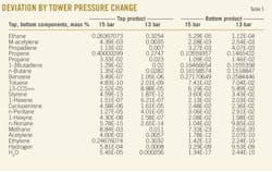
Fig. 3 shows the results of varying selected parameters with respect to H2S in the outlet gas and CO2 slip, comparing the MDEA system with and without DEA.
What do the results of the study tell? According to one popular process simulator, taking out a small amount (1.4%) of DEA shows a jump in CO2 slip, by an order of magnitude in some cases. Accompanying the CO2 rejection, however, the simulator also predicts a worsening of H2S concentration in the treated-gas outlet stream.
The simulation seems inconclusive, considering results from the other process simulators that either promised adequate slip, an adequate H2S outlet-gas specification, or both.
Are the results believable?
Operating experiences
Discussions with industry people indicated a consensus that small amounts of DEA in MDEA at high pressures could cause large amounts of CO2 pickup. A similar situation was experienced by a northern Alberta gas plant, initially slipping a high percentage of the feed CO2. In 1994, the plant operated at about 500 psig inlet pressure, processing some 25 MMscfd feed with 3.5 mol % CO2 and 1.5 mol % H2S. It was initially held that a small amount of DEA added caused the slip to decrease virtually to zero.
A second gas plant in central Alberta has a system of two HP amine contactors operating in parallel at about 1,000 psig and flow rate of about 180 MMscfd of 7% H2S and 5% CO2 feed. This plant, which initially had about 10% CO2 slip, went virtually to zero unexpectedly.
Upon analyzing the lean amine, the plant found it had been contaminated with small amounts of DGA and DEA thought to have come from cross contamination when the amine system had been topped up. (The concentration was suspiciously equivalent to a truckload of amine.) The CO2 slip has not improved back to the initial design levels; in spite of replacement of lost system amine over 11⁄2 years, the current DEA component being about 1.6%.
While the reported operating experience from two plants alone may not indicate DEA causing low slip operation, unofficial discussion with others in industry seems to substantiate this phenomenon. This led to speculation that any DEA in the mix will absorb most of the CO2 in addition to the H2S at high pressures.
The small amounts of DEA in solution appear to be able to pick up a disproportionate amount of CO2 in the solution mix, leading to speculation that DEA may be acting as a shuttle mechanism within the MDEA system. Subsequent discussions with commercial amine suppliers, however, failed to reveal any proposed mechanism to account for this apparent phenomenon.
Proprietary amine blends
Many MDEA suppliers have “doctored” their products with specific additions of primary and secondary amines, making them proprietary. In many instances, lab amine testing precludes reporting certain blends and, depending who does the testing and where the results are from, may exclude these specific known blended components or else provide component data as relabeled pseudonyms.
For example, it was speculated by one amine supplier that a component NMEA or MMEA could have been present but had not shown up in previous test reports. Specific testing for that component, although mentioned possibly being present, was not subsequently shared.
One process simulator vendor told of having certain components available in the simulator provided to special customers that were unavailable to general industry, the reason being that certain amine suppliers have developed specialized kinetic variables they are unwilling to share.
Other process simulator vendors have provided certain components in their packages that are not active. For example, it was found that Piperazine was included in one of the available process simulator components but was rendered inert because the equilibrium coefficients were not included.
DEA-MDEA model
First, the box presented in Part 1 (“Basic MDEA/DEA reactions,” OGJ, July 13, 2009, p. 48) is a look at the usual published MDEA/DEA chemistry. With MDEA in solution, the box shows the normal mechanism for H2S pickup.
DEA as a secondary amine can indirectly insert CO2 between its N-H bond, forming a carbamate via hydrolyzing first into water and bicarbonate.
The carbamate formed by this reaction is very stable, translating into more regeneration energy required (on average) for DEA in comparison with MDEA, which does not form carbamates due to its trisubstituted nature. (MDEA can only form various salts through acid-base equilibria.)
The presence of DEA in MDEA speeds up formation of bicarbonate, which otherwise has to be formed by the direct (but slow) reaction between CO2 and H2O, forming carbonic acid. DEA acts as a catalyst to the reaction of MDEA with CO2.
In studying the currently accepted mechanisms for CO2 and H2S interaction with secondary and tertiary amines and following discussion with industry representatives and a literature search (partially listed3 4) for a probable mechanism to account for Simonette’s zero slip, attention was focused on SN2 reactions.
SN2 reactions
The SN2 reaction (also known as bimolecular nucleophilic substitution) can occur when one of the atoms bonded to carbon is weak or highly polarized (i.e., making the carbon more electrophilic), potentially rendering this atom into a good leaving group. As an example, the bond between carbon-chlorine is highly polarized; the Cl– presents as a good leaving group because it is a stable anion in solution.
If NaOH is added into an aqueous solution of CH3Cl, the HO– (the nucleophile) will displace the chloride because the HO– anion is much less stable in solution than a chloride ion. This provides a rationale as to driving force of the reaction, in which thermodynamically more stable products are potentially made. This mechanism suggests that a probable model exists in which DEA contaminants may increase the pickup rate of CO2 in MDEA systems.
The actual SN2 reaction takes place in a single step as a concerted process. This involves simultaneous bond formation of the nucleophile to the carbon and bond breakage between the carbon and the leaving group. As the bond formation becomes more complete for the nucleophile, the bond breaking also becomes more complete for the leaving group.
This concerted process has an activation energy barrier that corresponds to some point along the reaction coordinate (i.e., the highest potential energy is reached at say, 50% new bond formation and 50% bond breakage).
This mechanism suggests a probable model exists in which DEA contaminants may increase the pickup rate of CO2 in MDEA systems. MDEA and other amines used in acid-gas removal processes are basic compounds and, as such, are in equilibrium between the protonated and nonprotonated state.
In its protonated form, the C-N bond to the methyl substituent becomes more polarized and weakened. Effectively, the methyl group is made more electrophilic and subject to undergo SN2 reaction with a nucleophile. As such, it may be that a reaction between the DEA carbamate anion as a nucleophile could occur in absorbers operating in higher pressure systems.
In this reaction, the methyl substituent of MDEA is picked up by the carbamate to form the methyl carbamate of DEA (see product diagrams, Fig. 4), which displaces another pseudo molecule of DEA, at which point the same reaction may be repeated until no CO2 remains.

This proposed pathway may explain why trace DEA impurities in MDEA bulk systems lead to large drops in CO2 slip, as the DEA present acts as a CO2 sink and is catalytic, such that each molecule of CO2 that is trapped leads to the formation of another molecule of free (pseudo)-DEA in higher pressure systems.
When we look at the DEA-carbamate molecule reacting with a protonated MDEA molecule, the SN2 reaction takes place at the methyl group carbon (Fig. 4b).
After reaction completion, the products shown in Fig. 4c would prevail.
Given a chain reaction of events starting with a small amount of DEA that quickly converted to carbamate and subsequently methylated (Fig. 4), could this provide a cascading effect of producing an unstable, pseudo-DEA capable of CO2 pickup from the protonated (thought to be a large fraction of the solution species) of MDEA?
This would certainly help explain why CO2 slip suddenly goes to zero when small amounts of DEA are present in solution. But large increases in the DEA component relative to MDEA of the regenerated rich amine (flowing back into the acid-gas stripper) should be detected at sampling points upstream if the process outlined were irreversible. This would most likely not be the case.
At the lower pressure and elevated temperature conditions of the regenerator, which drive off acid gases, the reaction solution becomes basic again. Under these reaction conditions, the methylated DEA carbamate could become demethylated by free DEA in solution, allowing the subsequent loss of CO2. Essentially, the regenerator would present conditions in which the favorable direction of reaction would be reversed.
In this manner, all MDEA would become regenerated, as well as the DEA impurity. Of course, without actual experimentation, the mechanism of this regeneration step is speculation and could proceed via another mechanism.
Nonetheless, the theory remains a plausible explanation for the decreased CO2 slip phenomenon.
Acknowledgments
Special thanks to Mark Conacher in arranging permission to present the material from the Suncor Simonette plant as well as to the plant personnel Lyle Leadley and Todd Kroeker who gathered, reviewed, and forwarded the data used. Thanks also to Jacobs Canada Inc. for use of the various licensed software in performing the simulation comparisons and to Rupert Wagner, BASF, for comments provided during compilation of the earlier version of this article.
References
- “Improved contactor removes more H2S,” Hydrocarbon Processing, May 2001, pp. 29-30.
- Weiland, Ralph H., “Tray Hydraulic Operating Regimes and Selectivity,” Laurance Reid Gas Conditioning Conference, Norman, Okla., Feb. 22-25, 2009.
- Lensen, Rob, “The promoter effect of piperazine on the removal of carbon dioxide”; http://www.bsdfreaks.nl/files/hoofd6.pdf.
- Little, R.J., Versteeg, G.F., and van Swaaij, W.P.M., “Kinetics of CO2 with Primary and Secondary Amines in Aqueous Solutions—I Zwitterion Deprotonation Kinetics for DEA and DIPA in Aqueous Blends of Alkanolamines,” Chemical Engineering Science, Vol. 47 (1992), No. 8, pp. 2027-2035.