Process developed for enhanced H2S recovery from sour-water strippers
Indian Oil Corp. Ltd. has developed a process for enhanced recovery of H2S from sour water of refinery hydrotreaters. The process Super Sour arrests the loss of H2S from feed the stabilization tank and result in recovery of H2S (7-10 wt % of H2S in feed) from sour-water strippers.
The Super Sour design configuration is being implemented at Gujarat refinery with start-up planned by yearend 2009.
The design has applications for other processes with high concentrations of H2S in water.
Controlling emissions
Stringent environmental regulations that emphasize controlling H2S/SO2 emissions in turn necessitate higher recovery of H2S from sour water in sour water stripper unit designs. Usually some amount of H2S is lost along with vent gases from the feed stabilization tank of stripper unit. This article describes a process design of a sour-water stripper to arrest the loss of H2S and recover it through simple and safe design.
Typically the feed stabilization tanks are designed according to API-650/620 to operate at a low pressure of 0.015-0.02 kg/sq cm (g) (0.21-0.28 psig). At this pressure, considerable amounts of hydrogen sulfide (H2S) are released from the tank due to its high vapor pressure. Traditionally, these vent gases from the tank are routed to the incinerator or stack of sulfur recovery units and are lost. The quantity of the unrecovered acid gas from the feed tank is around 10% of the sour-water feed’s H2S (depending on operating conditions). Some of the licensors utilize steam jet ejectors on the feed stabilization tank to suck these gases from the tank and recover H2S after employing a small amine scrubber downstream of the ejector with precise tank pressure-control system. In such designs, steam is required continuously for operation of ejectors, and the pressure of the tank must be controlled delicately at very low pressure.
Late in 2007, the process design engineering group of Indian Oil Corp. Ltd. developed a new and safe design process called “Super Sour” for one of its refineries’ new sour-water stripper plant. The new design ensures minimum H2S loss from the unit and meets environmental regulations.
This process employs installation of an additional hot-feed flash drum upstream of the cold-feed surge drum. The H2S rich vapors from the hot flash drum are routed to a small amine scrubber to absorb the liberated H2S. The H2S lean gas containing primarily hydrocarbons is then routed to the incinerator of the sulfur-recovery unit. The absorbed H2S in rich amine is recovered in the amine regenerator and is fed to the sulfur unit for converting to sulfur. Liquid hydrocarbon will continue to be separated in the cold-feed surge drum downstream to the hot flash drum.
The purpose of the hot flash drum is to liberate enough H2S from the feed sour water so that when the same is cooled and routed to the feed stabilization tank operating at almost atmospheric pressure, no H2S is lost from the tank.
This process does not involve additional continuous utility consumption (i.e., ejector steam) and precise suction pressure control scheme for the tank-ejector system. This will offer an intrinsically safe, simple, and efficient solution to arrest the loss of H2S and recover the same from feed stabilization tank.
Background
Refineries that process crudes containing sulfur will liberate the sulfur in various unit operations as H2S. Water-containing H2S (sour water) may contain other impurities, such as ammonia (NH3), phenol, CO2, and cyanides. Sour water is produced from most of the refinery process units, such as atmospheric and vacuum distillation units, hydrotreating units, hydrocrackers, steam crackers, and fluid catalytic cracking (FCC) units. Concentrations of both H2S and ammonia contaminants are highest in sour water generated from hydrotreating, hydrocracking, and FCC units.
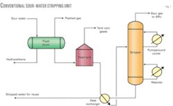
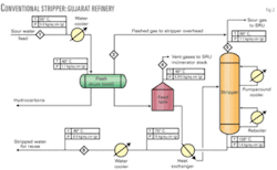
Reuse or disposal of such sour water containing H2S, ammonia, phenol, and cyanides requires removal of these contaminants from the water by the stripping process. The typical stripping process (Fig. 1) uses steam at the bottom of the stripper through a reboiler to force both the dissolved H2S and ammonia (NH3) out of the water into the gas phase for recovery of H2S in a sulfur-recovery unit (SRU).
The stripped water is usually reused as process water in other parts of the refinery units or otherwise sent to the waste-water treatment plant for further treatment before reutilization.
Conventional process
Fig. 1 shows a typical conventional sour-water stripper design. Before the stripper tower, sour-water feed is first pumped into the flash drum. This has two purposes:
- To remove hydrocarbon vapors.
- To remove hydrocarbon liquids.
The flash drum typically operates at low pressure (~0.7-1.0 kg/cc (g)) to flash off the lighter hydrocarbons. The flashed vapors are routed to a low-pressure system such as stripper column overhead, incinerator stack of an SRU after burning or acid flare. The liquid hydrocarbons are separated in the flash drum by gravity separation into the drum’s hydrocarbon collection compartment.
Sour water is then pumped to feed stabilization tank that is used to provide adequate residence time for additional hydrocarbon removal and for minimizing feed composition fluctuations because sour water is produced from different sources in a refinery. Significant compositional fluctuations cause poor stripping operation in the tower, resulting in either not consistently meeting product specification or wasting steam by overstripping. The constant feed composition and flow rate from the feed stabilization tank enables better control of the stripper tower and consistent stripped sour-water quality.
Sour water from the stabilization tank is heated in a feed-bottom heat exchanger by hot-stripped water from the stripper bottoms and fed to the tower as feed. As the sour water flows down the tower, H2S and ammonia are stripped off by steam or reboiled vapor from the bottom of the tower. Use of live steam as stripping agent adds more water to the tower.
Normally low-pressure steam is used in the bottom reboiler to generate vapor in the tower operating in the range of 0.7–1.2 kg/sq cm (g) top pressure. H2S, ammonia, and steam rise to the tower cooling section, which is controlled at 90° C. by pumped around cooler at the top of the tower. Low overhead temperatures, less than 80° C. can cause problems due to formation of ammonium salts that may plug process lines.
Sour gases containing H2S and ammonia from the top of the stripping tower are routed to the SRU.
The problem
Indian Oil’s refinery, in the state of Gujarat, was installing a new sour-water stripper unit as a part of residue upgrade. Currently the refinery operates four old sour-water stripping units based on convectional striping process designs.
The process objective of new sour-water stripper units in the residue upgrade project was to treat the sour water generated from the diesel hydro-desulfurization unit, vacuum gas oil hydrotreater, and isomerization unit for removing H2S and ammonia to meet stripped-water specification of less than 50 ppm (wt) H2S and ammonia.
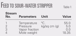
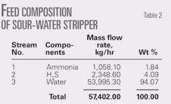
The new unit was to be designed to handle a total sour-water feed rate of 57,402 kg/hr (5.7 tonnes/hr) with composition as summarized in Tables 1 and 2.
Because the Gujarat refinery is already operating with four conventional units of sour-water striping process, the same was considered for the initial design of the new stripper.
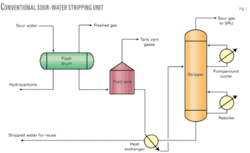
Fig. 2 shows flow of the initial design configuration of sour-water stripper unit for the Gujarat refinery, according to the traditional configuration.
In the conventional design, sour-water feed to unit arrives in the flash drum after cooling to 40° C. from 55° C. The feed is cooled to reduce the vapor pressure of sour water to minimize H2S loss from storage tank. The flash drum is floated with stripper column overhead, which is operating at pressure of 1.1 kg/sq cm (g). After hydrocarbon vapors are flashed off in the flash drum, feed enters the feed stabilization tank operating at almost atmospheric pressure condition (i.e., at 0.21335 psig pressure). The tank is designed according to API-650. At this low pressure, a considerable amount of H2S is released from the storage tank due to its high vapor pressure. The vent gases from the tank are routed to the incinerator of SRU and are lost. The loss is around 7.5% of the feed H2S (Table 3). Environmental regulations do not allow emissions of these vent gases containing H2S to incinerator stack or atmosphere because it leads to higher emissions of H2S and SO2.
New design
The new process design developed by Indian Oil, called Super Sour, for sour-water stripping ensures minimum or no H2S loss from the unit resulting in enhanced recovery of H2S compared with the traditional designs.
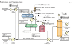
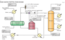
This process (Fig. 3) employs installation of an additional small-diameter hot feed flash drum (essentially, a typical vapor-liquid separator) upstream of cold-feed surge drum. The purpose of the hot flash drum is to liberate enough H2S from the sour-water feed so that, when it is cooled and routed to the feed stabilization tank (operating at almost atmospheric pressure) there will be no bleed of H2S from the tank, resulting in no loss of H2S from the tank.
In this design, the hot flash drum is held at around 60° C. by heating the sour-water feed with hot-stripped water coming from the outlet of feed bottom exchanger. This requires no additional hot utility.
The H2S rich vapors from hot flash drum are routed to a small amine scrubber to absorb the liberated H2S. The lean gas from absorber containing primarily hydrocarbons is then routed to the incinerator of the SRU. The absorbed H2S in rich amine is recovered in the amine regenerator and fed to the sulfur unit for conversion to sulfur.
Flashed feed from hot drum is cooled to 40° C. before being routed to the cold-feed surge drum for separation of hydrocarbon oil from water. This also reduces the vapor pressure of sour water. After separation of liquid hydrocarbon in cold-feed surge drum, sour water is routed to the stripper tower through the feed stabilization tank. The cold-surge drum and feed tank pressure is maintained by the nitrogen makeup.
Results
This design results in no loss of H2S from the feed stabilization tank, as the simulated numbers of Table 4 show. The electrolyte package of Chemstations USA (Chemcad V. 6.1) was used to model and simulate the sour-water stripper unit.
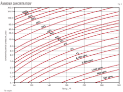
At the elevated temperature of around 60° C. of hot flash drum, the ammonia going to the gas phase from the hot drum will be very marginal (stream No. 2 of Table 4) due to its high solubility in water as compared with the H2S. Thus the ammonia buildup in the amine regenerator due to this approach will be insignificant. However, an ammonia purge stream from the amine overhead accumulator back to the cold surge drum of sour-water stripper is to knock off any ammonia buildup. Fig. 4 may be referred to for partial pressure of ammonia over aqueous solution.
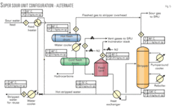
In an alternative configuration, vapors from the hot flash drum containing primarily H2S may be directly routed to the stripper overhead line for recovery of sulfur along with the stripper overhead vapors. This configuration does not require installation of a small amine scrubber column for absorbing the H2S from hot flash drum vapors. Fig. 5 shows the schematic of this configuration.
This configuration can be adopted where the likelihood of lighter hydrocarbon coming along with sour water is minimum or nil. Otherwise these hydrocarbons may find their way to the SRU, which will be detrimental to its operation.
null
References
- Meyers, Robert A., “Handbook of Petroleum Refining Processes,” 2nd Ed., New York: McGraw-Hill Professional Publishing, 1996.
- Newman, Stephen A., Sour Water Design by Charts (Part-1, Part-2, & Part 3), Hydrocarbon Processing, September 1991, October 1991, & November 1991.
The authors
Mukesh Kumar Sharma ([email protected]) is deputy manager (process design) for Indian Oil Corp. Ltd., New Delhi. He has 9 years of varied experience in process engineering, process simulations and design, troubleshooting, and optimization of various gas-liquid treating processes in petroleum refineries. Before joining the process design engineering group, he had worked as a senior process engineer at the Panipat refinery. He has also worked as a process engineer for crude & vacuum distillation units of the refinery. Sharma obtained his BTech (honors; 1999) in chemical engineering from the Institute of Technology, Varanasi, India.
Ashis Nag ([email protected]) has worked for Indian Oil for almost 32 years and at present heads its process design section. He has worked on different refinery units including reformers and hydrocrackers and carried out assignments in commissioning, operations, process design, and technical services. Nag obtained his BS (1976) in chemical engineering from Jadavpur University, Calcutta.
