AI improves fracturing performance
Key Highlights
- Automated fracturing systems use machine learning models trained on extensive historical data to optimize treatment designs in real-time.
- Electric frac spreads with centralized digital control enable seamless remote operation and rapid response to equipment or reservoir variations.
- Automation reduces manual pump adjustments, decreasing human error and increasing treatment consistency across stages and shifts.
- KPIs such as uniformity index, hydraulic efficiency, and screen-out risk demonstrate significant improvements with automation, including up to 78% fewer prematurely cut stages.
- Field case studies show automated systems placing a higher percentage of proppant and achieving more uniform flow distribution compared with manual control.
Automated fracturing addresses manual fracturing limitations by applying constant and nearly instantaneous control of the fracturing equipment for all stages. Automated fracturing controls pumping by using trained machine learning (ML) and artificial intelligence (AI) models based on real-time data.
Automation requires electric frac spreads to control closed-loop fracturing systems. These systems monitor and adjust pumps in real time based on optimization parameters and AI oversight. By 2022, systems were in place to automatically run fracture treatments on site, and by 2024 they began to perform automated, remotely monitored treatments. More than 25,000 stages had been autonomously completed by the end of first-quarter 2025. Key performance indices (KPIs) show that automated systems completed stages faster and with fewer screen outs than systems using manual control.
Automated fracturing
Traditional fracture treatments require manual control of slurry pumps, chemical metering pumps, proppant screws, etc. Alterations in pumping schedule during a job are determined by individuals on site based on fracture models or experience and are called out to individual pump operators. This process leads to variable approaches to treatment and lags between decisions and execution.
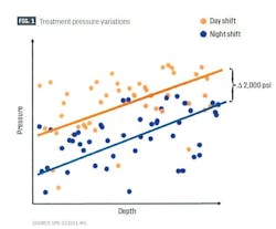
Fig. 1 shows human variability on the same frac spread working on a single pad. Despite similar downhole pressures, stresses, and other geological properties, surface treating pressures varied by about 2,000 psi between day and night shifts.
Automating the fracturing process addresses these inconsistencies by applying the same methodologies to all stages. Automated fracture treatments immediately alter the pumping job through trained machine learning (ML) models based on treating pressure and downhole fiber data using predefined subroutines to respond to variations in reservoir response.
Automated advantages could not be implemented until the advent of frac spreads using electric pumps. The control available from these pumps developed closed-loop fracturing systems by replacing local manual pump control with a single centralized digital control system.
These systems monitor performance and run-times of the pumps in real time, evaluate the total load required for the job design, and determine best distribution of the load across the entire system based on the optimization parameters given to it. Multiple sensors monitor the system in detail at several hertz to detect abnormal equipment conditions. The control unit instantly decides what remediation to take: whether to reduce rate on a suboptimal pump or isolate it altogether and then adjust other pump rates to compensate in a nearly seamless process.
Fig. 2 diagrams an electric fracturing spread. In general, the spread is laid out identically to a diesel-powered spread except with local power supplied either through the grid or local generation from turbine- or reciprocating engine-powered powerplants. The electric pumps on the spread, including sand blenders and chemical additive pumps, are individually monitored and controlled from the data van or at a client’s remote location through a dedicated communication link.
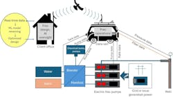
The control can be either manual or automatic, but for automated operations the data van typically runs the operation while the client’s remote location oversees and redesigns the job on the fly, if necessary.
A fully automated system requires a combination of real-time data acquisition, edge device computing, cloud computing, ML and AI tools, and AI-enabled equipment control. Edge-computing control handles routine tasks, but real-time ML learning and feedback is accessed remotely at the client’s office through the cloud, requiring robust, standardized communication and cybersecurity protocols between client and service company. The ML model consumes real-time data to improve frac designs on a stage-by-stage basis, and the AI provides real-time control of the fracturing job based on the revised ML treatment design.
Automatic control can rapidly detect individual pump failure and adjust spread pump performance to compensate. Given a desired treatment rate, the system will adjust each pump’s output to maintain the best distribution of load across the system based on trained ML models for each pump’s performance history. Given the interrogation frequency of the pump sensors, these adjustments are made quickly enough to be transparent to the overall rate output. This feature is also combined with pump operation schedules to determine when a pump needs to be isolated from the system either due to performance degradation below a set standard or for routine maintenance.
Fracture treatment ML development
Early tests of fracture automation were performed in the Bakken by Hess Corp. and Halliburton Co. The project aimed to automatically complete stage treatments using an intelligent fracturing algorithm which employed an ML predictive model to design, optimize, and alter a fracture treatment in real time based on received job data inputs.
The fracture treatment ML-learning algorithm trained on more than 150 wells using historical surface and subsurface data for treated wells and offset wells. Downhole and surface pressures, pumping rates, fiber, and microseismic data comprised the dataset. The model predicted pump-curve response based on the input variables, on a per stage basis, relative to original proposed design. In-well model improvements came from further training of the ML model during the first several stages in the well.
The model contained an optimization feature which designed jobs based on cost, time, rate, or pressure. Boundary conditions such as maximum allowable rate, pressure, slurry concentration etc. constrained the algorithm’s treatment choices.
Field tests combined ML design, real-time diagnostics, and fleet automation. Permanent fiber optic and pressure gauges installed on casing, combined with retrievable fiber optics and surface pressure gauges, provided data input into the system. An initial trial passively ran the model on an initial two wells and on the first 30% of stages in a third and fourth well.
The first two wells ran with the automated fracturing system but without optimized predictive model recommendations. The second two wells ran a check of optimizer adherence to boundary conditions and effective communications between the site supervisor, design engineer, and automated fracturing system operator before unleashing the system in full-autonomous mode.
The goal at this stage of the automated fracturing development was for the system to provide stage designs, control automated equipment during treatment, run the equipment using the predictive model, and consume data for model retraining for the next stage.
The automated system successfully placed fracture treatments. The ML predictive model received operational data and updated completion designs. Most of the updated designs came in time for the next stage. All boundary conditions were honored.
All 20 stages tested the predictive model designs against observed performance. At this early stage the blender was not automatically controlled or remotely monitored by the system and therefore required manual control.
The model designs were all significantly below the maximum allowable pressure boundary and did not use the full advantages of additional pressure. Most likely, large changes in design were required in the model’s optimizer to exceed a boundary condition. Revisions to the optimizer’s tool logic, run-times, and methodology addressed this issue in subsequent trials.
Automated fracturing KPIs
A 2020 automated fracturing study used uniformity index (UI) as a KPI to measure the success of the automated system versus manual fracturing control. This index evaluated flow distribution through clusters based on fiber distributed acoustic sensor (DAS) measurements. It used flow calculated from fiber data at each cluster and provides a value for the distribution of the flow among the clusters (Equation 1).
In a recent automated hydraulic fracturing paper, hydraulic efficiency (HE), proppant rate ramp-up index (RRUI), and risk provided the main KPIs guiding the automated process.
HE provided a consistency KPI by measuring the actual pumped slurry rate versus the designed rate (Equation 2). HE standard deviation or other variance parameters among stages indicate pumping consistency.
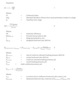
RRUI quantified lost time for the actual-rate ramp period in a treatment compared with an idealized ramp. This index requires a constant volume assumption, where only the rate changes between actual vs. idealized conditions. The rate ramp-period represents the time between when the rate first exceeds 15 bpm and when the rate first exceeds 95% of the maximum treatment rate. Given a maximum allowable wellhead pressure, the ideal wellhead rate equals the maximum achievable wellhead rate (Qat pressure).
The idealized ramp, however, may differ among operators depending upon their ramp-up philosophy as it relates to formation breakdown, or given other system constraints. Once this ramp is established, RRUI can be quantified within its family of idealized ramps.
A linear relationship between pressure and rate provides a curve to extrapolate idealized rate at the maximum allowable pressure (Qat pressure) based on the curve created from wellhead pressure at zero rate and wellhead pressure and pumping rate at a given timestep in the treatment. Equation 3 calculates Qat pressure.
For each timestep, Equation 4 calculates a time loss KPI by comparing actual flowrate against either the idealized rate or the maximum allowable design rate given system constraints other than maximum surface-treating pressure. These time losses were summed up within each rate-ramp period for each treatment.
Risk KPI is expressed as deviations in pumped proppant mass from designed proppant mass or stages cut short. Reducing a stage volume to avoid a screen-out or mitigate against a frac hit indicates a risk-management strategy in action. The automated system detects these deviations through rate reductions and proppant flushes.
Automated treatment
Automated treatment begins with traditional designs loaded into the system. Rules of engagement define maximum pump rates, fluid ramp-up rates, treatment pressures, slurry concentration, chemical loadings, etc. These rules are operator specific. Additional settings are in place for rate-control, proppant-staging and flush, friction reducer and other chemical injections, and screen-out risk management. These decisions are made at specific control points (Fig. 3).
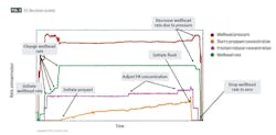
The system follows the entered design, but if the fully autonomous system is enabled, real-time treatment decisions are made by ML or AI algorithms based on fiber optic or pressure responses. The algorithms follow the operator’s general treatment guidelines but can respond nearly instantaneously, at least compared with manual control.
Case studies
A six-basin comparison in 2020 used permanently installed fiber optic cables to determine fluid and proppant distributions of almost 500 stages from nine unique formations. Fig. 4 shows the UI comparison among the basins from automated vs. standard stage treatments. The results show that the automated system improved UI by clustering more of the treatments around a higher UI than manual treatments.
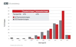
The top quartile of automated stages contained 63% of treatments compared with 49% for the standard treatments. With automated control in place, the worst performing stages saw UI improve from 0.1 with manual treatment to 0.4 with automated control.
Slurry rate control allocates rate setpoints to each pump to achieve the desired slurry rate. Rate setpoint changes provide an efficiency KPI. Table 1 shows wellhead rate setpoint KPIs in 2024 from five crews operating in four different basins which compare manual with automated fracturing responsiveness.

User requested wellhead rate setpoints count the number of rate changes manually applied over the course of a treatment stage. Executed pump-rate changes counts the number of rate changes sent to individual pumps from the central control system—manual or automatic—to achieve and maintain desired rate. For example, a change from 25 to 30 bpm would count as 1 setpoint change, but it could require dozens of individual executed pump rate changes to get to the new rate and to maintain the rate, depending on pump fluctuations.
Table 1 shows that, while in manual control, an average of 31 rate-setpoint changes per stage were sent, versus only 4 setpoint changes sent from the automatic system. Manual adjustment of pumps during these 31 changes resulted in 1,001 pump-rate setpoint changes, but the automatic system varied individual pump rates 14,348 times to precisely achieve, then maintain, the desired overall set pump rate. The automated system therefore required far less human intervention during the job and produced finer rate control.
Automated consistancy
The HE KPI tracked frac crew performance by normalizing changes in job design rates and volumes during more than a year of automated frac treatments by a single crew. This KPI was compared with treatment data from the preceeding 12 months using standard non-automated operations for wells in the same formation. Perforation depth bins of 1,000 ft categorized treatments, with bins only containing at least ten treatments for each dataset included in the analysis.
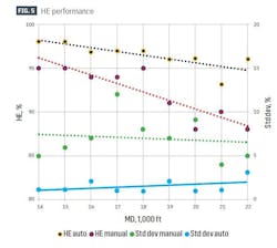
Fig. 5 shows per-bin HE between manual and automated fracture treatments. A negative correlation existed between hydraulic efficiency and stage depth for manual and automated treatments which was caused by higher friction pressure with increasing depth. In each measured-depth bin, however, automated stage data had higher HE with smaller standard deviations around the trendline. Overall, HE improved 4.6% using the automated system.
Fig. 6 shows time loss vs. ideal based on RRUI. This metric was determined across multiple crews, but the figure shows a typical example from only one crew. The data revealed efficiency gains through improved rate control from the automated system during each ramp. On average, the automated system improved ramp-up time by 44%.
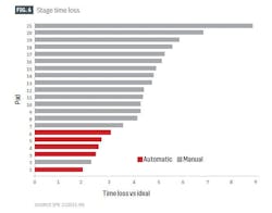
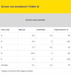
Table 2 lists frac stages cut short as an indicator of early screen-out risk avoidance. When early screen-out appears as a risk during the job, common practice dictates ending the stage before the designed proppant mass is placed. In this study, a premature stage is defined as one which ended with less than 80% of the designed proppant mass placed.
Jobs with fewer cut-short stages indicate jobs executed with less risk. Five frac crews obtained data for this metric, normalized by 1,000 stages pumped. The results show that the automated system decreased stages cut short during the jobs by an average of 78%.
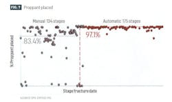
These results followed earlier successes in eliminating screen outs in a Haynesville-Bossier study. These high formation-stress shales occasionally produced premature screen outs. The automated rate control system took advantage of a correlation between screen-out tendencies and the number of clusters accepting fluid to rapidly adjust rate to prevent screen outs by breaking down more clusters and placing more proppant evenly along the lateral.
Fig. 7 shows that the automated system eliminated screen outs and increased the percentage of proppant placed. Manual control placed an average of 83.4% of designed proppant/stage whereas the automated rate-control system improved average proppant placed to 97.1%.
Bibliography
Bogle, E. and Stark, P., “Improving Consistency and Control in Completions,” SPE-223511-MS, SPE Hydraulic Fracturing Technology Conference and Exhibition, The Woodlands, Tex., Feb. 4-6, 2025.
Butler, E., Pertuso, D., Hua, G., and Stark, P., “Automated Hydraulic Fracturing Integrated with Predictive Machine Learning,” SPE-209165-MS, SPE Hydraulic Fracturing Technology Conference and Exhibition, The Woodlands, Tex., Feb. 1-3, 2022.
El-Sayed, M., Abdelhalim, M., Seada, M., Mahmoud, B., Farouk, E., and Bapetco, A.M., “Applications of Intelligent Formation Breakdown Automation Algorithms in Tight Formation for Creating Conductive Propped Fractures, Improving Pumping Efficiency and Maximizing Hydrocarbon Productivity,” SPE-218506-MS, SPE Conference at Oman Petroleum & Energy Show, Muscat, Oman, Apr. 22-24, 2024.
Holley, E., Martysevich, V., Cook, K, and Gale, S., “Using Automation While Pumping to Improve Stimulation Uniformity and Consistency: A Series of Case Studies,” SPE-199742-MS, SPE Hydraulic Fracturing Technology Conference and Exhibition, The Woodlands, Tex., Feb. 4-6, 2020.
About the Author

Alex Procyk
Upstream Editor
Alex Procyk is Upstream Editor at Oil & Gas Journal. He has also served as a principal technical professional at Halliburton and as a completion engineer at ConocoPhillips. He holds a BS in chemistry (1987) from Kent State University and a PhD in chemistry (1992) from Carnegie Mellon University. He is a member of the Society of Petroleum Engineers (SPE).