Wired drill pipe improves real-time drilling communication
Based on “Improved Drilling Operations and Wired Drill Pipe and Along-String Measurements – Learning and Highlights from Multiple North Sea Deployments,” SPE/IADC-204029-MS, SPE/IADC International Drilling Conference and Exhibition, Virtual, Mar. 8-12, 2021.
Wired drill pipe (WDP) increases downhole communications and functionality over current mud-pulse telemetry (MPT). High data speeds and along-string measurement (ASM) subs display real-time downhole measurements at rig site and remote operation centers. Better understanding of downhole conditions optimizes drilling practices, increases drilling speed, reduces wellbore instability, and produces longer wells.
From 2017 to 2020, wired drill pipe has been deployed on five rigs in the North Sea for more than 50 wells, covering 145 well sections and 120,000 m of drilled hole. Depths up to about 7,500 m have been drilled using the system in both exploration and development wells.
Researchers from Equinor ASA and NOV Inc. discussed how real-time WDP measurements improved drilling performance, operational efficiency, drilling time, and well placement in a recent paper at the SPE-IADC virtual International Drilling Conference and Exhibition. The system is the basis for drilling automation and is part of Equinor’s digital initiative.
Wired pipe
Conventionally, communication between surface and bottom hole assembly (BHA) is through MPT, which is limited to 4-40 bits per second (bps) and is affected by flow rate, well depth, and fluid characteristics.
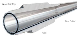
WDP has an embedded wire with inductive couplers at each end which provide high-speed telemetry of up to 57,600 bps (Fig. 1). The inductive coil eliminates requirement for wire alignment during makeup. No special doping methods are needed, and standard operations such as cementing, dropping balls, and pumping pills and darts can be performed like with normal drill pipe.
The integrated wired system consists, from bottom to top, of an interface sub, repeater subs, ASM components, modified top drive with cabling to interface between drill stem and rig floor, and a surface computer network (Fig. 2).
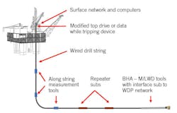
The interface sub establishes bidirectional communication between WDP and measurement/logging-while-drilling (M/LWD) tools. ASM components include high-frequency sensor packages which collect annular and internal pressures, temperatures, rotation, and three-axis vibration measurements. Larger collar-based designs above the BHA can include the regular ASM package plus downhole torque, weight on bit (WOB), and bending moment sensors.
Repeater subs are placed along the drillstring about every 300-400 m to amplify the signal. The bidirectional signals can be sent down from surface to actuate downhole tools as well as up from tools for data collection and analysis.
Connection to surface typically is through the top drive, but a new data-while-tripping (DWT) device enables connection to the WDP system during handling by the elevators. It has a remotely operated retractable arm mounted on top-drive bails. The device has an option to collect WDP information while tripping without connecting to the top drive, monitoring real time surge and swab effects, which are important during high-heaves or narrow mud windows.
Case study
The WDP system was used in a field in which the operator plans to drill and complete more than 100 wells in the next 12-14 years. Phase 2 development so far has drilled slightly more than 29,000 m of formation with 29 WDP runs. Signal uptime has been 97% (Equation 1) with 2,297 possible data hours and only 62.75 signal downtime hours.

Results from Phase 2 with WDP were compared with Phase 1 drilled using only MPT. Metrics for comparison included drilling distance, open hole time, on bottom rate-of-penetration (ROP), and time to circulate hole clean.
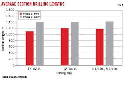
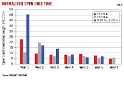
Fig. 3 shows average drilling distances for 17 ½-in., 12 ¼-in., and combined 9 ½-in. and 8 ½-in. hole sections. Open hole times, measured as time spent between drilling a new formation until casing or liner is landed, are shown for seven wells in Fig. 4. A short open hole time indicates the section was drilled with high ROP and in good enough condition to immediately run casing and liner. Phase 2 wells monitored with WDP had 27% longer sections on average with reduced normalized open hole times.
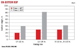
ROP rose by an average of 114% during Phase 2 (Fig. 5) over Phase 1, which was limited due to the need to obtain logging data with slower MPT technology. Using WDP’s high-speed data acquisition, ROP could be increased while maintaining quality data acquisition. ASM tools continuously evaluated downhole conditions while drilling, including vibrations and hole clean-out.
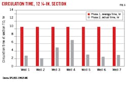
Time spent circulating the hole clean after drilling a section to TD generally was shorter using WDP. For 17 ¼-in. and 8 ½-in. hole sections, average drilling times were about the same between Phase 1 and Phase 2 (albeit with 28% longer drilling sections in Phase 2). But times greatly improved in the 12 1/2-in. hole section, dropping 63% while drilling 23% longer sections (Fig. 6).
Reservoir drilling
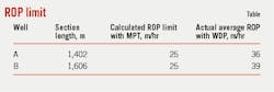
Semisubmersible Rig B drilled two reservoir sections in a field development in the Norwegian Continental Shelf (NCS) with plans to drill and complete 24 wells with an option for eight more. The wells were drilled with advanced LWD tools and WDP. Drilling speed was limited to a maximum of 60 m/hr. Results comparing WDT ROP data with calculated ROP using MPT are shown in Table 1. WDP is estimated to increase ROP by at least 10 m/hr.
Over 2,965 downlinks have been sent using WDP on Rig B. Downlinks using WDP do not compromise bandwidth due to higher data rates available versus MPT. Drilling is not interrupted for taking surveys because mud pump cycling is not needed. In weak formations, pressure fluctuations from MPT can potentially produce hole instability, and extended circulation can produce washouts when downlinking using MPT while the string is stationary.
WDP reduces open hole time by monitoring rotational checkshots with MWD survey tools at TD and while circulating the hole clean. Increased direction control is maintained with higher data transfer rates. Up to 30 downlinks have been sent while drilling one stand, and an average of 79 downlinks per 1,000 m drilled have been sent out, maintaining tight control over trajectory.
String vibration
An excess of stringers caused problems drilling the 17 1/2-in. section in Phase 2, resulting in negative drilling breaks and increased lateral vibrations. The section is typically drilled in two runs, mostly tripping because of steering-tool failure. High lateral vibrations in this section were identified as chaotic whirl in the BHA. Vibrations were most severe drilling through stringers which required higher WOB. Drilling factors which result in whirl include high side and friction forces at the contact point, lack of stiffness of the BHA, and high rpm.
These factors were addressed by switching to higher-weight drill pipe. On Well 1, vibration measurements were available from the entire drillstring through WDP, providing for real-time downhole observation of surface drilling adjustments. Fig. 7 (left) shows high lateral vibrations in the well using 5 7/8-in. high-weight drill pipe (HWDP). On Well 8, the 17 ½-in. BHA included stiffer 6 5/8-in. wired HWDP, and this damped most of the vibrations, as shown in Fig. 7 (right). Section TD was reached in one run.
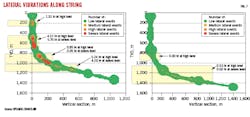
Vibration risk remained through stringers and was managed by limiting WOB when vibrations were detected through ASM tools, which have update rates of 2 sec compared with 150 sec for MPT.
Hole cleaning
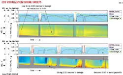
When pumping a sweep pill in a conventional string, equivalent circulating density (ECD) is monitored in BHA and surface standpipe pressure sensors. BHA data is limited in resolution by the MPT. Only several datapoints per minute can be transferred.
WDP provides both annular and internal pressure measurements distributed along the string. Annular pressure measured at each sensor position is translated into an ECD (both circulating and static) and plotted in real time as a heatmap.
Pill location and cuttings distribution can be tracked as a function of changes in ECD over time. Cuttings build-up due to poor hole cleaning can be quickly observed and located via high differential pressures between two sensors.
Fig. 8 shows ECD responses along strings when pumping sweep pills. The upper chart shows negligible increase in ECD. Cuttings are removed as they are generated. ROP can be increased without compromising hole cleaning. The lower chart illustrates poor hole cleaning, with significant increases in ECD observed in the heat map. This condition requires reducing ROP to prevent a pack-off.
Wellbore stability
WDP was used for drilling and monitoring a dedicated clean-out run. Monitoring the operation in detail prevented a potential plug and abandonment.
After drilling the 12 ½-in. section, the wellbore was left open for five days to perform wireline logging. A cleanout assembly was run in the well to displace the well to lighter fluid before running casing.
A first cleanout run to set 9 5/8-in. casing attempted to circulate bottoms up at 3,600 l./min with the bit at the shoe. A surge event was observed on both ASM tools even with string speeds as low as 30 m/min, but equivalent mud weight (EMW) remained below the maximum 1.60 s.g. established by a formation integrity test at the 14-in. casing shoe.
Losses to formation and 18% gas observed in returns required spacing out the drillstring and circulating bottoms up through choke and kill lines with closed BOP. Annular pressures from BHA and ASMs were continuously monitored to adjust surface choke settings during circulation. EMW reduced as flow rate was staged up, with gas returns measured and reported. Gas migration up the annulus was tracked by local EMW as measured by ASM tools. A flow check showed when the well was static, and the assembly was subsequently pulled out of hole.
While tripping out, small swab events were identified on downhole EMW measurements, with variations up to 0.1 s.g. Although not of magnitude to damage the wellbore, the cyclic nature of the pressure changes over a long duration could lead to formation stress.
The 9 5/8-in. liner was subsequently run in-hole, but losses were encountered when it reached the 14-in. casing shoe. The riser was displaced to a lighter fluid before pulling the liner out, limiting further losses. It was assumed that the well had been fractured while running the liner, and the well had to be swapped to a lighter fluid to account for the revised 1.38-1.39 s.g. fracture-balancing gradient.
A second cleanout run was performed by running in-hole to specified intervals and displacing 1.44 s.g. mud with 1.30 s.g. fluid. Continuous monitoring of downhole pressures ensured that fracture gradient was not exceeded.
Fig. 9 shows the well profile and location of ASM tools for the second cleanout run. One sensor was above the 14-in. casing shoe to ensure EMW could be interpolated at the shoe. Upon reaching the shoe, the well was displaced to 1.30 s.g. fluid. Fluid in the riser was 1.20 s.g, and upper pressure gauges showed EMW’s reflecting the lighter column (Fig. 9, lower chart). Because of these differences, the enhanced measuring system showed a decrease in total EMW while ASM1 and ASM2 first showed an increase in EMW related to higher proportion of heavier mud in the annulus. Once the heavy mud reached the tool’s position, EMW decreased, and the annulus was displaced to 1.30 s.g. This continued until all sensors recorded 1.30 s.g., indicating full displacement.
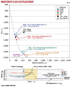
ASMs show in detail the advance of the displacement in real time. Flow rate was adjusted based on these measurements and downhole EMW never exceeded fracture limits. The 9 5/8-in. liner was successfully run and cemented in place with only limited losses.
Bibliography
Fosse, M., “Wired Drill Pipe Technology: Technical and Economic Overview,” Master’s Thesis, University of Stavanger, 2015.
Nygård, B.E., Andreassen, E., Carlsen, J.A., Ulfsnes, G.A., Øksenvåg, S., Stabell, R., Davis, T., Naterstad, T.N., Zainoune, S., and Vandvik, E., “Improved Drilling Operations and Wired Drill Pipe and Along-String Measurements – Learning and Highlights from Multiple North Sea Deployments,” SPE/IADC-204029-MS, SPE/IADC International Drilling Conference and Exhibition, Virtual, Mar. 8-12, 2021.
Salomone, A., Burrafato, S., Maccarini, G.R., Poloni, R., Gioia, V., Concas, A., Tangen, G.I., Huse, A., Antoniani, L., Anderson, M., and Zainoune, S., “First Wired Drill Pipe Deployment in Adriatic Sea,” SPE-197833-MS, Abu Dhabi International Petroleum Exhibition & Conference, Abu Dhabi, Nov. 11-14, 2019.
About the Author

Alex Procyk
Upstream Editor
Alex Procyk is Upstream Editor at Oil & Gas Journal. He has also served as a principal technical professional at Halliburton and as a completion engineer at ConocoPhillips. He holds a BS in chemistry (1987) from Kent State University and a PhD in chemistry (1992) from Carnegie Mellon University. He is a member of the Society of Petroleum Engineers (SPE).