New surface-choking model simplifies sour-gas production
Fan Yang
Wenlong Jia
Changjun Li
CNPC Key Laboratory of Oil & Gas Storage and Transportation
Langfang City, China
Yubin Wang
Xin Ouyang
PetroChina Pipeline R & D Center
Langfang City, China
A new method controlling pressure drop across chokes has been successfully applied to a high-pressure sour gas well in Sichuan basin, China. High-pressure sour gas wells use multistage choking methods to step down high wellhead pressures and safely flow gas into low-pressure surface gathering systems. Pressure drop across each choke valve is kept relatively low to avoid uncontrollable Joule-Thomson temperature drop and hydrate blockage. However, this method requires a complicated choking process and additional surface equipment.
Controlling pressure drop across the valve with respect to choking temperatures and hydrate formation prediction can simplify choking. The new process saves surface construction investments and reduces operation risk for high-pressure sour gas wells.
Current choke method
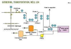
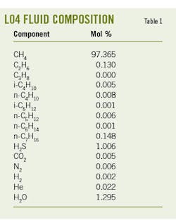
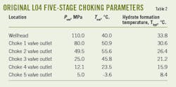
Natural gas produced from high-pressure Well L04 mixes with liquid water and sour gas components such as hydrogen sulfide (H2S) and carbon dioxide (CO2) (Table 1). In comparison with low-pressure natural gas wells, surface gathering and transportation for L04 is complicated and includes one water-jacket heater, a five-stage choking train, and other equipment (Fig. 1). Wellhead pressure is 110 MegaPascal (MPa) but working pressure of gas gathering is 5 MPa. Natural gas flows from the wellhead into the three-stage high-pressure choke manifold with 140 MPa maximum design pressure. Gas pressure at the outlet of the three-stage choke manifold drops below 32 MPa. From there, gas flows through the fourth-stage choke valve. The temperature at the outlet of this valve is near hydrate formation temperature.
To prevent hydrate blockage, a water jacket heater and hydrate inhibitor injection pump are applied to heat the gas or inject inhibitor at the outlet of the choke valve. Natural gas next enters the fifth-stage choke valve where pressure drops to 5 MPa. It then flows into subsequent low-pressure surface gathering and transportation. Table 2 lists operating parameters of L04.
Simplified choke method
A new method proposed to simplify the choking process considered the maximum choking pressure drop without dropping temperatures to hydrate formation levels.
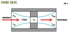
The choking pressure-drop model uses the two-phase flow method. The schematic diagram of the choke valve is shown in Fig. 2. Pressure drop across the choke valve reaches maximum value, the critical flow velocity, when fluid flow is choked. For single-phase gas flow, critical flow is where maximum gas velocity across the valve is equal to its sonic velocity.4 However, for gas-liquid two-phase flow, critical flow velocity is much lower than sonic velocity, and pressure drop calculations across the valve are complicated. Here, the non-equilibrium homogeneous (HNE-DS) model calculates maximum pressure drop, and the method has been adopted in ISO 4126-10 for computing mass flow of two-phase flow and for sizing safety valves and nozzles.5
The HNE-DS model sets the minimum valve outlet pressure (Pout) equal to critical flow pressure (Pc) at the critical flow rate. Maximum pressure drop can be calculated from the difference between choke valve inlet pressure and Pc calculated from the HNE-DS model. Additionally, accuracy of the model is enhanced by using a boiling delay coefficient to describe the non-equilibrium gas-to-liquid condensation phenomenon.
Based on the above models, the reasonable pressure drop across each choke valve is determined using the following procedures:
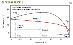
- Calculate choking temperatures by obtaining total fluid enthalpy from fluid composition, inlet temperature (Tin), and inlet pressure (Pin) of the choke valve. Fluid temperature is calculated at different choke valve outlet pressures by the multiphase isenthalpic flash method. Relevant results are shown in Fig. 3 (black curve).
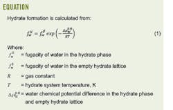
- Calculate hydrate formation conditions by constructing a hydrate formation curve (Fig. 3, red curve), calculating fluid hydrate formation temperatures at different pressures and comparing results with choking temperatures obtained in Step 1. Find the hydrate formation pressure and temperature constraint point (Phyd) from the intersection of the choking temperature curve and hydrate formation curve.
- Determine maximum pressure drop across the choke valve by calculating Pc from Pin, Tin, and the HNE-DS model. When Pc is higher than Phyd, there is no hydrate formation even if pressure drop across the choke valve is set to its maximum value (Pin-Pc). Otherwise, the outlet choke valve temperature will be lower than the hydrate formation temperature and maximum pressure drop can only be set to a value less than Pin-Phyd. To avoid hydrate formation within the next choke valve, gas should be heated, or hydrate inhibitor should be injected, at the inlet of the next valve where pressure is just above Phyd. For subsequent choking processes where inlet pressures are below Phyd, the HNE-DS model is repeated to get Pout of the next choke valve until Pout is equal to the operating pressure of surface gathering equipment.
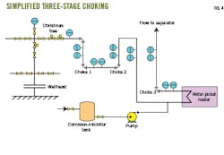
Fig. 3 provides the process for determining pressure drop across each valve. This method reduced the original five-stage choking process to a simplified three-stage process (Fig. 4).
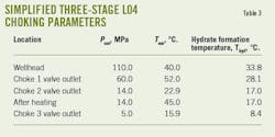
Tables 2 and 3 supply the wellhead and choke outlet pressures of all original and simplified choke valves. Results show that the choke pressure-drop in the optimized process is around 50 MPa compared with about 20 MPa in the original five-stage process. As shown in Fig. 3 and Table 3, hydrate prevention measures are still required in the simplified process, and the water jacket heater is retained at the inlet of the third-stage choke valve.
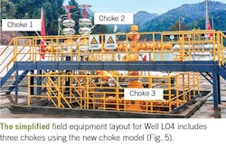
The new three-stage choking process not only reduces the number of choke valves and other equipment (Fig. 5) but also eliminates one field operator. This new process has operated safely for more than 1 year with no hydrate blockage accidents.
References
- Jia, W., Yang, F., Wu, X., Li, C., and Wang, Y., “Predictions on temperatures of high-pressure gas/water/MEG mixtures flowing through wellhead chokes,” Journal of Natural Gas Science and Engineering, Vol. 74, November 2020, pp. 103-108.
- Li, Z., You, J., Jia, W., and He, Y., “An improved Parrish-Prausnitz (PP) model to predict the hydrate formation condition of natural gas with a high volume content of CO2,” Journal of Natural Gas Science and Engineering, Vol. 37, January 2017, pp. 479-486.
- Lasich, M. and Ramjugernath, D., “Clathrate hydrates modelled with classical density functional theory coupled with a simple lattice gas and van der Waals-Platteeuw theory,” Philosophical Magazine, Vol. 96, No. 27, August 2016, pp. 2853-2867.
- Bahadori, A., “Estimation of flow coefficient for subsonic natural gas flow through orifice-type chokes using a simple method,” Journal of Natural Gas Science and Engineering, Vol. 9, November 2012, pp. 39-44.
- Diener, R. and Schmidt, J., “Sizing of throttling device for gas/liquid two-phase flow part 2: Control valves, orifices, and nozzles,” Process Safety Progress, Vol. 24, No. 1, March 2005, pp. 29-37.
The authors
Fan Yang ([email protected]) is studying for his PhD at Southwest Petroleum University (SWPU). He holds an MS (2020) in petroleum engineering from SWPU.
Wenlong Jia ([email protected]) is associate professor at SWPU. He was a post-doctoral fellow at the Department of Petroleum and Geosystem Engineering, The University of Texas at Austin. He has a PhD (2014) in petroleum engineering from SWPU and is a member of Society of Petroleum Engineers (SPE) and American Chemical Society (ACS).
Xin Ouyang ([email protected]) is a senior engineer in PetroChina Pipeline R&D Center. He has a PhD (2010) in petroleum engineering from Dalian University of Technology. He is a member of Chinese Petroleum Society (CPS).
Yubin Wang ([email protected]) is a senior engineer in PetroChina Pipeline R&D Center. He has an MS in petroleum engineering from Guangzhou Institute of Energy Conversion, Chinese Academy of Sciences. He is a member of CPS.
Changjun Li ([email protected]) is a professor at SWPU. He has an MS (1987) in petroleum engineering from SWPU. He is a member of CPS.
