Advanced simulation increases drift diameter using RSS or mud motors
Gabriel Teodorescu
Stabil Drill Specialties
Houston
Advanced engineering simulation and predictive modelling allowed for the development of an efficient tool for increasing drift diameter during and after drilling operations using rotary steerable system (RSS) tools or mud motors. Rather than using a concentric reamer that follows the spiral developed when using an RSS tool, an eccentric reamer knocks off the ledges and micro-doglegs, increasing drift ID.
Well-known models for rock crushing were coupled with a finite element method to develop a reamer-rock interaction model. The model predicted resultant axial forces and lower reactive torque. These were validated through numerous field runs. Statistical analysis further revealed the tool’s reaming efficiency in a high dogleg severity (DLS) borehole in terms of removing ledges and increasing drift diameter while providing a lower reactive torque as compared with conventional eccentric reamers. As a result, hook loads tripping out are lower and more consistent, paving the way for an economic casing operation.
Background
Predictive modeling is a well-known technique to simulate loads, stresses, and strains as well as fluid dynamics for downhole tools. When it comes to simulating cutter-rock interaction on a downhole tool the details can be problematic, especially when the rocks have anisotropic properties and behave differently at various depths without laying in perfect planes.
The bottom-hole assembly (BHA) used, depth, formation drilled, mud system, tool positioning within the BHA, well inclination, geological borderlines, and dogleg severities, coupled with operational parameters, can also introduce uncertainties when trying to model behavior of a reaming tool within the drill string.
Drilling with a motor or an RSS tool, the drill bit creates wellbore tortuosity due to RSS design, making it difficult to run liners or set casing after drilling a section. A typical directional driller will run a dedicated reamer to clean up the ledges and doglegs to help save time on casing installation and improve overall wellbore quality.
Most reamer designs involve an eccentric blade that extends out from the main body and, while providing wellbore coverage, generates high reactive torque and high vibrations. Reamers also must be stabilized to minimize damage to the tool and surrounding BHA components.
Based on extensive field studies and advanced predictive modeling to evaluate rock damage, engineers have developed a helical eccentric reamer that generates substantially lower reactive torque as compared with existing eccentric designs. Due to the tool being dynamically balanced and both 180° apart from and further up the reaming section, it can be run while drilling.
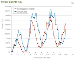
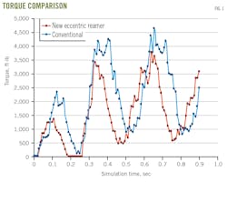
Modeling a 12-in. spiral pitch profile into the rock, with unconfined compressive strength (UCS) of 18,000 psi—like that of cartage rock—allowed proper simulation of cutting action. Fig. 1 shows a 20-30% difference in reactive torque between the helical design and conventional eccentric reamers.
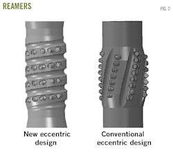
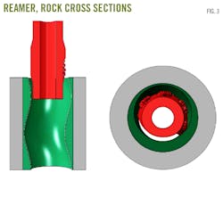
Fig. 2 compares the new eccentric reamer and a conventional eccentric reamer. Fig. 3 depicts the model setup via cross-sectional view through longitudinal and transversal planes, showing a typical RSS-tool generated pattern.
Using a 3D analysis of rock cutting and removal with both eccentric reamers, and a Drucker-Prager model to evaluate damage to the rock, predictive modeling simulated borehole cleaning, axial force, and torque. Other parameters used in the simulation were rpm (60) and rate of penetration (ROP, 240 feet/hr).
Fig. 4 shows the axial force generated during reaming. The volume of rock removed by the reamer during the cutting process was used to evaluate design efficiency in terms of cleaning up the wellbore and opening the drift ID. In convential eccentric reamer designs the axial force vibrates more vigorously due to a more complex contact between the borehole and the reamer.
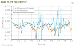
The proprietary design of the new eccentric reamer uses a helical blade which progressively engages the rock as the reamer advances, matching the ROP and generating a lower reactive torque and a smooth wellbore profile. While removing about the same amount of rock and enlarging the drift diameter, the new eccentric reamer removes rock in smaller pieces, minimizing resultant reactive torque. The smaller cuts also diminish inherent vibrations and associated drilling dysfunctions, such as backward whirl.
The higher magnitude and fluctuation appear in Fig. 4, the conventional eccentric design having a higher working band than the new reamer. This behavior is associated with tool bounce and weight transfer issues, leading to poor tool performance. The smaller the axial fluctuation, the smaller the bounce, and the greater the efficiency. The tool was deployed in the field for multiple trials and surface data validated the numerical prediction, registering lower torque than the conventional eccentric reamer.
Field testing
An Eagle Ford operator needed better borehole quality to ease tripping out after drilling with an RSS tool in an environment with severe doglegs. It used the new reamer with well and BHA configuration as follows:
- Measured depth = 10,000-13,962 ft.
- Hole size = 6.75 in.
- Weight on bit (WOB) = 10,000-30,000 lb.
- Torque = 6,000-12,500 ft-lb.
- Maximum DLS = 15.64°/100 ft.
- Tool rotation = 60-80 rpm.
- Mud weight = 9.8 gpm.
- ROP = 75 ft/hr.
The main dogleg severity was about 2°/100 ft and the curve started at 12,000 ft, while the maximum DLS was at just below 13,000 ft measured depth. Performance analysis included: drilling (dedicated drill-out BHA), reaming (reamer BHA), and tripping in after reaming (tripping in with dedicated drill-out BHA to continue drilling).
Drilling and reaming quantification used only the torque values and the number of times (counts) these values were reached. This approach looks at the tool behavior from a statistical standpoint, such as a histogram, and identifies the energy consumed during a certain drilling or reaming operation, which in turn relates to tool or hole cleaning efficiency.
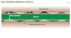
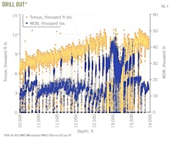
Fig. 5 shows the toque and WOB values during drill out for the entire section under evaluation. Notice the erratic behavior of the operating parameters as the curve builds and approaches the high dogleg severity area. Torque constantly increases with depth due to increasing drag, peaking out at just above 12,000 ft-lb, with fluctuations between 2,500 and 12,000 ft-lb, while WOB varies between 5,000 and more than 40,000 lb, especially in the high DLS section (around 13,000 ft).
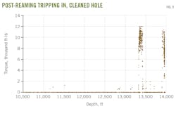
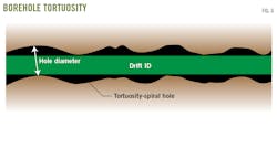
Fig. 6 represents a typical borehole profile, outlining tortuosity.
The drift ID is smaller than the borehole diameter, due to the ledges and micro-doglegs created when using an RSS tool or a mud motor, making it difficult to trip out BHAs, clean up the hole, and set casing.
Following drilling, the BHA was tripped out and the new eccentric reamer was placed in the BHA to ream the section. BHA configuration was: Bit-Bit sub-Spiral drill collar-New reamer-Pony collar-Stabilizer-Drill collar-Stabilizer-Drill collar-Stabilizer- XO sub-DP to surface.
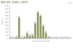
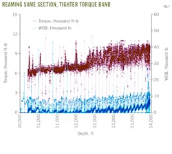
Fig. 7 outlines the reamer run, plotting WOB and torque versus measured depth and showing lower (at similar rpm) and tighter torque values and lower fluctuations coupled with lower WOB (since this is a reaming operation, rather than a drill ahead operation).
Borehole tortuosity generated by the RSS tool is reduced by the eccentric reamer for this section by increasing drift diameter, cleaning up ledges, and improving the line of sight to allow for an easier and more cost-efficient casing. Fig. 8 shows the borehole profile after reaming.
After the section was reamed, the BHA was tripped out and original drilling BHA tripped in, the torque required to go through the tight spots also being recorded. Fig. 9 shows these values. No torque is visible in the curve buildup but some remains, as expected, in the area with the highest dogleg severity (15.64°/100 ft).
Statistical analysis
Proper evaluation of the tool’s reaming action required further dissemination of the torque values recorded on the electronic data recorder (EDR) and dividing the reaming depth interval into multiple sections. Considering curve building started around 12,000 ft, a greater degree of reaming activity was expected past that point and into the zone where high DLS occurred.
The torque values recorded per various sections generated an equivalent histogram for values greater than 2,000 ft-lb and up to 12,500 ft-lb. Analysis showed that decreasing the torque magnitude and the number of counts for each value equated to less energy spent conditioning the borehole.
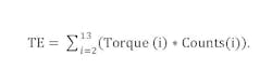
Employing a similar concept in which the energy put into the system is required to cut and remove the rock, a torsional energy (TE) factor, considering only torque and counts of the corresponding values, quantified energy content based on the torque.
The concept looks at torque alone, addressing not only rock-removing by way of shearing but also progressive engagement into the rock. The progressive engagement results in lower torque values as compared with conventional eccentric reamer designs.
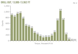
Fig. 10 shows torque values and counts (broken down in 500 ft-lb gradations) for the drill out between 10,500 and 11,000 ft (DLS = 2.08°/100 ft).
The following formula quantifies the energy dissipated during the drill-out section, reaming, and tripping in post-reaming, as torsional energy:
Torque values are divided into bins, starting at 2,000 ft-lb in this case and ending at 13,000 ft-lb. All the values encountered during that depth section between 2,000 and 2,499 are in the 2,000-ft-lb torque bin as a statistical approximation, etc.
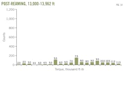
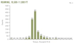
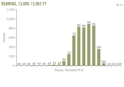
To validate proper reaming activity, post-reaming activity evaluation used the same TE term (Table 1). Fig. 11 shows the torque values recorded for this section. Post-reaming represents trip in after reaming is complete. Torque associated with that tripping operation shows additional “drilling” that was necessary due to improper reaming.
While the highest torque count is the 6,000-ft-lb bin for the reaming operation (as compared with 7,000 ft-lb for the drill out), the torsional energy for reaming is about half that of drilling. Moreover, there were no torque values greater than 2,000 ft-lb for the post-reaming operation, pointing out to the tool’s efficiency.

The drill out BHA was directional (Bit-RSS-MWD-Stabilizer-Drill collar-Stabilizer-Filter sub-Crossover) while the reaming BHA was designed to hold the curve, having three stabilizers (more drag) instead of two: Bit-Bit sub-Drill collar-Reamer-Collar-Stabilizer-Drill collar-Stabilizer-Drill collar-Stabilizer-Crossover.
Figs. 10 and 11 show torque counts during curve buildup, starting at 12,000 ft, for drill out and reaming respectively. Higher torque values occurred during drill out—9,500 ft-lb vs. 6,500 ft-lb. during reaming—while no torque values greater than 2,000 ft-lb were recorded during post-reaming operations. Table 2 shows the TE values for this depth section.
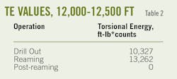
The highest DLS for this section was 3.5°/100 ft. Reaming was 30% more energetic, pointing out the cleaning operation of increasing the borehole’s drift diameter. Similar behavior occurred up to 13,000 ft. The final part of the analysis focused on 13,000-13,962 ft, in which the highest DLS was encountered (15.64°/100 ft).
Figs. 12-14 show drill-out, reaming, and post-reaming. Table 3 shows the energy content associated with these operations for the last section of the well, 13,000-13,962 ft.
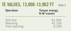
Intense activity occurred during drilling (TE = 61,504), reaming (TE = 41,100), and even post-reaming (TE = 6,160). Due to high DLS, energy dissipation during both drilling and reaming activity was also expected to be elevated. Some torque related activity was also present during post-reaming (tripping in), demonstrating that high dogleg severity calls for either more time or higher rpm when running a reamer.
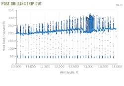
Another detail further validating the eccentric reamer’s cleaning efficiency is hook load, which is lower while tripping out after reaming than tripping out after drill-out and has limited fluctuations. A lower and constant hook load indicates better borehole quality, which in turn translates into more efficient casing.
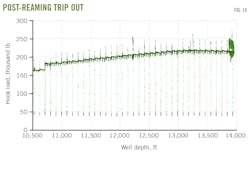
Figs. 15 and 16 show hook load during tripping out from drilling and tripping out from reaming, respectively. Efficient reaming allows the BHA to trip out easier due to a cleaner borehole. Notice elevated values (> 320,000 lb) and higher fluctuations (> 50,000 lb) when tripping out the drilling BHA as compared with the reaming BHA.
The author
S. Gabriel Teodorescu ([email protected]) is engineering and technical services manager at Stabil Drill Specialties, a division of Superior Energy Services, in Houston, Tex., responsible for strategic technology development, manufacturing improvement, and operational excellence. He served as senior technical manager at Halliburton, engineering manager at National Oilwell Varco, research and development manager at Weatherford International, and senior product development engineer at Hughes Christensen, a division of Baker Hughes. He holds an MS (1997) in mechanical engineering from Craiova University, Romania, and a Ph.D (2002) in materials engineering from Auburn University in Alabama. He is a licensed professional engineer in the state of Texas and is a member of SPE, ASM, and ASME.