Innovations push Åsgard transport system to start up
Based on a presentation to the World Gas Conference, Nice, June 6-9, 2000.
The Åsgard transport system in the Norwegian North Sea began operating in October 2000. It uses several new technologies developed specifically for it, including multi-diameter pigs for commissioning and operational cleaning and inspection.
The field tie-in is by a subsea riser manifold, which can be operated and maintained by ROVs. The cleaning and inspection pigs will be launched subsea through a removable pig launcher.
The 42-in. Åsgard system is moving rich gas from the Åsgard offshore field outside mid-Norway to the Karstø gas terminal for further processing.
The pipeline has been built with excess capacity and prepared for future fields to be tied in both at the upstream end and at several locations along the pipeline. The Norne, Draugen, and the Heidrun fields will be connected.
The technological achievements of this project, discussed here, have implications for future developments of deepwater gas gathering systems.
Åsgard
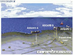
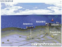
The Åsgard field is a large offshore gas, oil, and condensate field west of mid-Norway in water about 300 m deep (Fig. 1). The field development consists of an oil producing ship (Åsgard A) for processing and export of oil, gas injection and transfer of gas to the field gas center, which is a large semi-submersible platform (Åsgard B), and a unit for storage and offshore loading of the condensate and oil (Åsgard C).
Subsea completed wells are tied back to either Åsgard A or Åsgard B. So far this is the largest subsea development in the world with about 50 subsea wells, more than 300 km of infield flow lines and 160 km of umbilical for operation of the subsea wells.
Flexible risers connect Åsgard B to the 28-in. subsea gas riser base that guide the gas export to the 42-in. pipeline terminating at the Karstø gas processing terminal.
The floating gas center, Åsgard B, is a semi-submersible platform with a total dry deck load of 33,500 tonnes, and a displacement of 82,000 tonnes. Connecting this platform to a large-diameter pipeline on the seabed 300 m below the surface was among the larger technical challenges in the Åsgard project.
An array of three 14-in. flexible risers connects the topside gas-export manifold to the subsea riser base at the upstream end of the Åsgard gas transport pipeline.
Two of the new and challenging technical elements were:
- The large-diameter (14 in.) flexible risers for high pressure and temperature service.
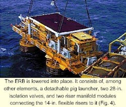
- The gas-export riser base (ERB) with a subsea pig launcher and necessary components to fulfill the requirements for maintenance and repair.
These two critical elements were part of a much larger technology development and qualification program undertaken by the project. The purpose of the program was to develop solutions and components to satisfy the functional requirements and environmental exposure in the Haltenbanken area.
Considered here will be some of these challenges, in particular the connection between Åsgard B and the Åsgard transport system and how pigging and inspection requirements are accommodated.
Further information on the field development is available in Carlsen.1
Transportation system
The Åsgard transport system is primarily a 707-km gas-gathering pipeline connecting the Åsgard field to the gas-treatment plant at Karstø.
The pipeline is designed for a capacity exceeding the Åsgard field gas production rates, and this implies that other gas producing fields can be linked to the system.
Transportation arrangements have already been made for connecting the Norne, Heidrun, and Draugen fields to the system via subsea T-connections. In addition, six T-connections have been installed along the Åsgard transport pipeline to allow for future tie-ins of other fields.
The Åsgard system starts with the ERB structure connecting the 14-in. flexible risers to the Åsgard transport pipeline. The ERB lies 500 m from the Åsgard B platform. The first 200 m of the pipeline have a diameter of 28-in. connected directly to the 42-in. pipeline through a short 28 and 42-in. transition piece.
The pipeline route is basically parallel to the coastline southwards to the landfall at Karmøy, where a landfall valve station is located to separate the offshore and onshore pipeline. The design pressure of the offshore pipeline is 212 bar and 172 barg for the onshore pipeline.
Design
In the conceptual phase of the system, the Åsgard transport pipeline was designed only to meet the need for export of more than 381 bcf/year sales gas from the Åsgard field to processing at Karstø. A 36-in. pipeline with a design pressure of 190 barg was sufficient to accommodate these volumes.
A desire for the system to be able to handle future fields and to serve as a trunk line in the Haltenbanken area led to the decision increase the pipeline diameter to 40-in. and later with Europipe II to 42-in. and 200 barg.
Additional increase in capacity has been obtained by utilizing some of the initial corrosion allowance to increase the design pressure to 212 barg. The estimated capacity for the pipeline is now more than 670 bcf/year sales gas, approximately 80% higher than the initial requirement from the Åsgard field.
The design pressure of the onshore pipeline, 172 barg, was chosen as a cost-effective alternative compared to the initial design of 200 barg.
The onshore pipeline is protected against the pressure from the offshore pipeline by closure of the landfall emergency valves and isolation of the onshore pipeline when the pressure at the landfall exceeds given pressure set points.
For long pipelines such as the Åsgard transport system, gas temperatures can go below the ambient temperature due to gas expansion. The need for the ability to transport future volumes exceeding the initial design led to a minimum design temperature reduction from initially 0° C. to -10° C.
The pipeline is designed for slightly sour service and is capable of transporting gas with up to 6 mole % CO2 and 50 ppm H2S. This improves the corrosion protection and allows for some flexibility in the offshore gas conditioning.
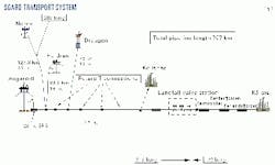
The main design parameters for the Åsgard transport pipeline system (Fig. 2) are the following:
- Design capacity: 67 million std. cu m/day.
- Design pressure: 212 barg offshore, 172 barg onshore.
- Maximum design temperature: 60° C.
- Offshore water depth: 60-375 m.
- Dense-phase gas: maximum cricondenbar 105 barg.
- Minimum operating pressure: 112 barg.
- Service: Slightly sour (steel Grade X-65, modified).
- Corrosion allowance offshore pipeline: 1.5 mm.
Design pressure
The Norne field is about 120 km north of the starting point of the Åsgard transport pipeline. To maintain the maximum transport capacity in the Åsgard system, the export pressure at Norne and Heidrun will be higher than the Åsgard transport-pipeline design pressure of 212 barg.
The design pressure for the Norne and Heidrun pipelines is therefore set at 280 barg.
A conventional system design would require an over-pressure protection facility at the subsea tie-in point for the Norne-Heidrun pipelines to the Åsgard pipeline. Instead, an alternative over-pressure protection system has been chosen for this tie-in point to avoid complicated subsea installations.
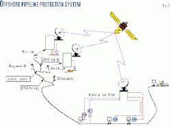
In short, this alternative over-pressure protection and safety system is based on monitoring the downstream pressure at the landfall valve station, communicating these data via satellite, and initiating an automatic shutdown at the upstream fields when the pre-set pressure limits are exceeded.
Lund explains the principle of this system.2
The gas volumes from the Norne and Heidrun fields are small compared to the Åsgard volumes, and it will take several hours from downstream blockage to occur until the pressure build up to a level exceeding the limits.
Fig. 3 illustrates the offshore pipeline-protection system.
Export riser
Norway requires all pipelines to be piggable.
In addition, a specific feature mandates a baseline inspection program within the first 2 years of operation, and later runs at regular intervals.
Even though the value of a baseline inspection can be argued, Statoil believes that intelligent pigging is of great importance for the safe operation of subsea pipelines.
For the Åsgard pipeline in particular, certain operational aspects underline the importance of being able to pig the pipeline:
- The transport specification allows for a slightly sour gas service.
- The gas is rich, and if pressure drops below the cricondenbar, pigging might be required to remove all of the liquid.
- In normal operation, the TEG contactor on Åsgard B performs drying. Some carry-over into the gas stream is expected.
Based on these operational aspects, the following specifications were established for the Åsgard transport pigging requirements:
- Pigging during the commissioning phase for cleaning and water removal.
- Inspection pigging with a 5-year period.
- Cleaning pigging on an average once per year.
In addition to the pigging requirements, the following main functional requirements were considered essential for the subsea ERB:
- 50-year lifetime design, with higher than 99 % regularity.
- All components to be maintainable.
- All subsea operations to be diverless and ROV based.
- Gas shall continue to be exported through the ERB during normal maintenance situations.
- For change out of critical components (assumed to be very rare), a close down of the gas export is acceptable.
- Subsea pig launching shall be performed from the ERB.
Even though some valuable experience has been gained in previous projects (mostly related to commissioning of small diameter pipelines), it is a considerable step forward in technology to realize the subsea pigging for the Åsgard transport pipeline.
A major program was initiated in an early phase of the project in order to qualify the key technology components. The pipeline size considered at that time was 40-in.
The elements of the qualification program were maintainable 40-in. subsea double expanding gate valve; 40-in. subsea pig launcher; 40-in. mechanical clamp connectors; remotely operated 40-in. high pressure isolation plug; and remotely operated clamp connecting-disconnecting tool
The functional requirements listed above and further optimization of the concept led to the final ERB (Fig. 4).
In principle, the ERB consists of a detachable pig launcher, two 28-in. isolation valves, two riser manifold modules connecting the 14-in. flexible risers to the ERB, a supporting frame including a 28-in. header, and three mechanical connectors.
Pigging tool
In parallel to the ERB development program, work was initiated to identify solutions to connect the Norne and Heidrun fields to the Åsgard transport system (Fig. 2).
Among the ideas generated was the possibility of completely eliminating the subsea pig-launching concept by extending the Åsgard transport pipeline northwards to the Heidrun field and use of the Heidrun TLP as the starting point for the pipeline.
Limitations imposed by Heidrun prevented extending the 42-in. pipeline. The preferred size of the Heidrun riser was 20-in., but later studies showed that this could be extended to a maximum of 28-in. with the use of the existing slots and riser hang-off system on the platform.
A two-diameter pipeline system, 28-in. to 42-in., was therefore considered a possible alternative, if pigging and internal inspection requirements could be solved.
An idea of using a dual-diameter system was discussed internally and with potential vendors for pipeline inspection services. These discussions were the background for a 1-year feasibility study, including construction of prototypes of key components for testing purposes.
To test the mechanical robustness of the pigs thoroughly, Statoil built a separate test loop.
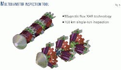
It was required to develop pigs and inspection tools that could travel safely through both pipeline diameters without damage and the meshing mechanism through the transition zones should prove smooth and reliable. It was a further requirement that the tool should be able to inspect both the 28-in. and the 42-in. pipeline in one run.
Through the detailed design phase of the MDPT, the magnetization unit has changed considerably, and the concept is now based on the use of smaller and stronger magnetic bars compared to the original design.
It was accepted to use the same magnets both in the 28-in. and the 42-in. section because the magnetic flux level was satisfactory both in the 28-in. and the 42-in. pipe.
After this change, there will now be a true multi-diameter pigging tool (Fig. 5) available, capable of handling diameters within 28-42 in. This tool will be ready for use for baseline inspection in summer 2001.
Combined solution
The studies and the test of the MDPT tool and the studies and evaluated bids on the ERB made possible several alternative system solutions for the Åsgard transport pipeline system.
Due to a number of time-limiting factors, it was impossible to proceed with the MDPT alternative with an extension of the Åsgard pipeline with a 28-in. section to Heidrun.
The potential and feasibility of 28-in./42-in. multidiameter pigging tool were convincing, however, and the partners of the Åsgard transport license adopted a revised concept based upon a 28-in. ERB solution in the vicinity of Åsgard B and the use of MDPT for the subsea pig launching.
Future connections
Along the pipeline, eight Ts have been installed. Four are of a hot-tap design, and the others are installed with valves, connectors (for tie-in of branch lines), and protection structures.
All Ts are designed for diverless connection of branch lines. The Ts were installed as complete units from the laybarge.
When the relatively light and compact hot-tap Ts were installed, it was observed that in deep water the pipeline rotated significantly. With the much larger and heavier 16-in. valve Ts, it was considered that this could become a very difficult problem and a lot of work was performed in order to explain this rotational behavior.
Under a theory, the Ts were installed with buoyancy to take the weight and the eccentric loading the Ts represented to the pipeline. The four valve Ts were installed without rotation.
The difference in T design is related to the expectancy in utilization. The valve Ts are located in the northern end of the pipeline where the three fields (Heidrun, Norne, and Draugen) already are planned to be connected to the pipeline.
Buckling
The maximum design temperature for the Åsgard field gas export is 60° C. This temperature together with the high pressure might create global buckling of the first 70 km of the pipeline and would result in unacceptably high bending moments.
Traditional pipeline buckling prevention by rock dumping would require very high rock-protection volumes due to the very uneven sea floor. An alternative approach based on displacement control has therefore been implemented.
It is well known that the compressive axial force caused by pressure and temperature in an axially restrained pipeline may be substantial and may create buckling of the pipeline, provided a sufficient axial imperfection is present.
If buckling is initiated, axial feed-in and the corresponding bending stresses and strains may be significant. This is evident from other large-diameter gas pipelines operated by Statoil (Zeepipe IIA and IIB).
Where the seabed is uneven, these pipelines have now formed buckles locally with lateral displacements up to 10-12 m, steered in accordance with the design by local gravel cover.
This design has also been implemented for the Åsgard pipeline, resulting in less than 10% of the rock dumping volumes compared to the traditional fully restrained design. Holme presents further details.4
Landfall solution
Landfall solutions at the western coast of Norway have been performed in rock caverns as piercing chambers, using large concrete plugs as barriers to sea. The duration of the construction periods has been long because of the civil and mechanical works involved in the piercing chamber, which is narrow with limited space. All traditional pull-in operations have been performed with assistance from divers and with the winch located on the lay vessel.
The landfall for Åsgard transport is in an existing tunnel; the pipeline is taken into the tunnel at 60 m water depth. As an alternative for this project, a seal tube system was implemented to avoid the use of divers.
The seal tube was anchored to the rock surface and a pilot hole drilled from the seal tube into the sea. Reaming up to 1.6 m was performed with the same seal tube with the drilling rig installed inside the tunnel.
After pipeline pull-in, the pipeline was grouted to the rock for the entire section allowing the seal tube to be disconnected and the offshore pipeline to be welded to the landfall tunnel pipeline.
Commissioning
With only the downstream end of the offshore pipeline accessible above water, it was decided to conduct all pre-commissioning and commissioning activities from the landfall end, but a complicating element was that the upstream end of the pipeline contracted into a 28-in. section.
Statoil developed pigs capable of contracting from a 42-in. diameter pipeline into a 28-in. pipeline.
These multi-diameter commissioning pigs have proven capable of traveling 700 km in the 42-in. pipeline and the 28-in. upstream end section of the Åsgard transport pipeline.
References
- Carlsen, H., Huus, O., Mosbergvik, O., "The Åsgard Field Development," World Gas Conference, Nice, June 6-9, 2000.
- Lund, S., Gjertveit, E., Bratseth, A., "Pipelines with Two Design Pressure Levels," Deep Offshore Technology Conference, 1997, The Hague.
- Svendsen, C., "Multi Diameter Pigging," Eurogas-99, Bochum, May 25-27, 1999.
- Holme, R., Levold, E., Langford, G., Slettebø, H., "Åsgard transport. The Design Challenges for the longest Gas Trunkline Norway," Offshore Pipeline Technology Conference, Amsterdam, February 1999.
- Gjertveit, E., Sjøen, K., Eide, L.O., "Pipelines for Deep Waters," Deep Offshore Technology, Oct. 19-21,1999, Stavanger.
The authors
Erling Gjertveit since 1995 has been chief engineer of pipeline technology in Statoil. He has been involved in many of the major pipeline projects from the Norwegian sector of the North Sea, among them as engineering manager for Zeepipe I (1989-92) and as construction manager for the Europipe I (1992-95). Gjertveit joined Statoil in 1976. Gjertveit received training as a civil engineer at the Norwegian Institute of Technology, Trondheim, in 1972.
Karl Sjøen in 2000 became senior advisor for conceptual engineering at Statoil. He was first employed by Statoil in 1983 and has been involved in design, construction, and operation of many of the pipeline systems from the Norwegian Continental Shelf. In 1991, Sjøen became chief engineer in transport and system technology and in 1998 was appointed project manager for subsea gas export installations at the Åsgard field.
Sjøen holds an MSc (1978) and a PhD (1983) in mechanical engineering from the Norwegian Institute of Technology, Trondheim.
Lars Olaf Eide since 1996 has been project manager for the offshore pipeline of Åsgard transport. From 1975-82, he worked for the Norwegian Petroleum Directorate, the Norwegian petroleum regulatory body. Since 1982, Eide has worked for Statoil in various positions related to pipeline design, construction, and operation. He holds a BSc (1975) in civil engineering from Sunderland Polytechnic (UK).
