Global positioning technologies provide essential exploration tool

Simon Corbett, Martin Rayson
Quality Engineering & Survey Technology Ltd.
Newcastle, U.K.
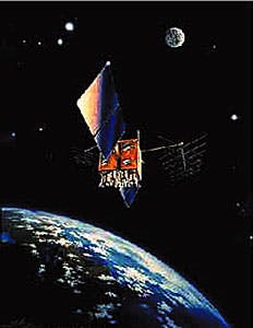
The Navstar GPS system, consisting of 24 operating satellites, provides sufficient coverage of the Earth so that signals can be received almost anywhere in the world at any time. The satellites are arranged in six orbital planes with four satellites located in each plane (Fig. 2).Global positioning system (GPS) technologies provide an essential tool for surface exploration activities.
This technology, and derivatives thereof, can be used for a whole host of applications, including dynamic positioning of drillships, semisubmersibles, and pipeline laying vessels.
In addition, the technology can be used to spot wells, map geologic formations, track and guide oil tankers, and provide geospatial coordinates for instruments used in seismic surveys.
This article describes a number of commercial and government DGPS services used primarily for the offshore hydrocarbon exploration and production industries.
The benefits of subscribing to these systems include:
- A reduction in equipment and costs
- More complete coverage
- No need to coordinate reference stations
- Immediate positioning.
History
In the 1960s, the U.S. Air Force and Navy began developing a space-based positioning service, with the potential for worldwide, continuous, all-weather tracking system. The U.S. Navy sponsored two projects: Transit Doppler and Timation. Transit became operational in 1964 and was made available to civilian users in 1967.At the time, the U.S. Air Force simultaneously tested a 3D navigation system known as System 621B. On Apr. 17, 1973, a memorandum was sent by the U.S. Deputy Secretary of Defense to the U.S. Air Force agreeing to combine the Timation and System 621B concepts into a comprehensive Department of Defense system, named Navstar GPS.
The Navstar GPS Joint Program Office (JPO) was established on July 1, 1973, to manage the new system at the U.S. Air Force Systems Command's Space and Missiles Systems Organization (now known as the Space Systems Division), located at Los Angeles Air Force Base in California.
In December 1973, the Joint Program Office began the first of the four phases of the Navstar GPS program. Now fully operational, GPS provides suitably equipped users with accurate 3D positions, velocity, and time parameters.
The service allows for simultaneous, unlimited numbers of users and is provided globally, continuously, and throughout all weather conditions. Today, GPS allows for instantaneous positioning to within an accuracy of 100 m (95%) in the horizontal and 140 m (95%) in the vertical for most commercial activities.
GPS constellation
GPS comprises three major segments: space, control, and user ( Fig. 1 [43,459 bytes]). The role of the space segment is to provide a sufficient number of satellites such that a receiver may observe four satellites anywhere in the world at any time.To obtain this coverage, the GPS constellation consists of 24 operating satellites (Fig. 2 [15,830 bytes]). The 24 satellites are arranged in six, near circular orbital planes with 4 satellites located in each plane. All of the orbit planes have a nominal inclination relative to the equator of 55° and an orbit height of almost 20,200 km (10,900 nautical miles).
This height is such that the satellites take one-half sidereal day to complete an orbit; therefore, the satellites follow a ground track that repeats every sidereal day (about 23 hr, 56 min).
The control segment, or Operational Control System, encompasses a master control station, five monitor stations, three ground antennas, one prelaunch compatibility station, and a network of communication lines that connect the master control station to each of the other components.
The main functions of the control segment consist of tracking the satellites for orbit and clock determination, prediction modeling, time synchronization, and data uploading to each satellite.
The master control station is located in the Consolidated Space Operations Center (CSOC) at the Falcon Air Force Base, Colo. It is the central processing unit and is manned 24 hr a day, 7 days a week.
The monitor stations are located at the Falcon Air Force Base, Hawaii, Ascension Island, Diego Garcia in the Indian Ocean, and Kwajalein in the North Pacific Ocean. These are unmanned stations that operate via remote control from the master control station.
The GPS user segment consists of a number of military and civilian receivers that can receive, understand, and process the radio frequencies transmitted by the GPS satellites. They may be used for a variety of applications such as navigation, positioning, time transfer, surveying, and attitude determination.
Because GPS is a military system, the user segment comprises all the equipment for positioning and navigation with GPS for the U.S. Department of Defense National Defense Program. However, with the growing use by civilians, there are now many different manufacturers of GPS user equipment for both military and commercial activities.
GPS accuracy
One of the most interesting (yet often misunderstood) features of GPS is the enormous range in the accuracy with which it can be utilized. It ranges from 100 m to 1 mm-a total of five orders of magnitude.No other surveying system offers such possibilities, and the key to the potential user is to identify the positioning requirements in order to obtain the most suitable system. There are essentially two methods of positioning with GPS using either pseudoranges or carrier phases. However, the differences between these two are becoming less distinguishable.
See the box "GPS SYSTEMS" on p. xx for an overview of GPS positioning technologies, equipment requirements, and an indication of costs.
Differential GPS
The oil and gas industry requires sub 5-m positioning for a number of applications, including construction, seismic surveys, pipe-laying operations, and rig moves. Arguably, the oil industry can take credit for developing DGPS, currently the most sophisticated form of GPS positioning technology available for commercial application.For the oil and gas industry, DGPS typically provides a horizontal positional precision of 1-5 m (95%).
Because there are difficulties over radio licensing and distances between reference and mobile receivers, a number of companies have established DGPS services. Such services comprise a network of reference stations constantly transmitting encrypted DGPS corrections via land or satellite-based radio communication links.
Users of the system subscribe to the service, allowing them to demodulate and unscramble the incoming signal and feed the corrections into a GPS receiver, or third-party software. The companies providing these services rigorously monitor the condition of their service, such that they have the ability to provide GPS alerts and support various backup facilities in case of hardware failure.
System service providers
There are a number of DGPS service providers. For example, the U.S. Coast Guard (USCG) operates a free maritime DGPS service, broadcasting differential corrections from a number of reference receivers around the U.S.Horizontal positioning is guaranteed to 10 m (95%), and integrity alerts within 10 sec. The USCG DGPS system was originally planned to cover only coastal and Great Lake regions; however, this has now been expanded to cover inland waterways. It was expected that by late 1998, the USCG service would achieve full operational capability.
In addition, Racal Survey provides a satellite-based DGPS service, known as Land Star. It provides a service throughout North America, Australia, Europe, South Africa, New Zealand, and Indonesia. Land Star is a wide area DGPS service comprising 19 virtual reference stations and 5 physical reference stations.
DGPS corrections are generated at each of the reference stations, combined, then uplinked to a high-power Spot beam satellite. Users are equipped with a receiver and antenna to receive both the GPS signals and the DGPS corrections from the Land Star satellite. The service costs about $500/ day.
Fugro also operates a similar satellite-based DGPS service to Racal known as OmniStar. For North America, OmniStar comprises 11 base stations distributed across the U.S. Data from each base station are sent to a control center in Houston where they are uplinked to a high-power, spot-beam satellite.
Corrections are received from the satellite, decoded, and applied by the user. OmniStar provides coverage over the entire continental U.S. southern Canada, and northern Mexico.
Alternatives
Other alternative systems that may soon become viable include the Russian and European satellite systems. The Global Navigation Sputnik System (Glonass) is the Russian equivalent to GPS. Satellite launches began Oct. 12, 1982, and more than 70 now orbit the earth. As of May, only 15 satellites were in operation.For many offshore markets such as the North Sea, companies anticipate using Glonass as a redundant system in case the Navstar system becomes inoperable.
The European Commission (EC) also recommended in early 1999 that the European Union (EU) develop and implement both space and ground segments for its next generation Global Navigation Satellite System (GNSS-2). It has been suggested that GNSS-2 be linked with Glonass. This alliance or even a standalone Galileo system would have both positive and negative consequences for GPS.
On one hand, if the Galileo satellites broadcast GPS signals, it would greatly improve the availability, integrity, and robustness of the system. On the other hand, if the system is not fully compatible, it could be seen as a didrect competitor.
A note of caution
Although GPS offers many benefits over traditional survey techniques, it is also a system that should be treated with a great deal of care. For example, setting up a high-resolution form of GPS, such as a differential GPS (DGPS) network, can be difficult and expensive, requiring expert geodetic knowledge.For long-term projects, however, the costs can be reduced-considering subscription rates to the commercial systems are about $400/day-using specialized geodetic software and correct initialization procedures.
The benefits then include control over the DGPS service (local to the area of operation), in-house quality control, and the ability to relocate the DGPS reference stations after work has ceased.
However, like all technologically advanced systems, gross and systematic errors can be readily introduced from the peripheral systems such as GPS receivers and navigation software associated with offshore operations.
For example, a recent rig move performed in the North Sea encountered an error of 130 m, introduced as a result of operator confusion. The client required the rig position to be reported in the local ED50 datum, which necessitated a mathematical conversion of geographic coordinates from the WGS84 datum to the ED50 datum, using a standard set of transformation parameters (OGJ, July 6, 1998, p. 72).
During the survey, a type of GPS receiver was used that allowed datum transformation parameters to be entered into the receiver. This resulted in the receiver outputting coordinates referenced to the local ED50 datum rather than WGS84 datum.
The coordinates were then imported into a real-time navigation package also configured to perform the same datum transformation. This caused a double transformation of surface coordinates, resulting in a 130 m displacement of the rig from its true surface location.
End-of-week roll over
A few seconds after midnight Aug. 22, 1999, Universal Time, the GPS week will roll over from 1023 to zero. The event has been slightly less published that the Year 2000 rollover; however, GPS users should still be aware of the potential issues arising from the problem.All GPS measurements are made with respect to GPS time that is kept by a combination of the ground monitor stations and satellite atomic clocks. GPS Time is related to the global Universal time (UTC) to within 1 microsec; however, unlike UTC, it is continuous.
Leap seconds are inserted into the UTC time scale to approximates the Earth's rotational period with respect to the Sun. Therefore, although GPS time was synchronized with UTC at its onset, because there are leap second insertions, GPS time is now ahead of UTC by 13 sec. The last common epoch between UTC and GPS Time was midnight Jan. 5/6, 1980.
The largest unit of GPS time is 1 week (or 604,800 sec). In other words, GPS times are referenced to by seconds of week and number of weeks since GPS time zero, beginning Jan. 6, 1980 (Table 1 [25,209 bytes]).
Both the seconds of week and GPS week number are contained in the broadcast navigation message from each satellite. The problem arises because only 10 bits are used to represent the GPS week. Thus, the largest possible week number is 1023 (210-1).
Therefore, at the end of week 1023, at midnight Aug. 21/22, 1999, the GPS week number will roll over to zero. If GPS receivers do not take this event into account, they will assume it is midnight Jan. 5/6, 1980, and could potentially output an incorrect position.
Most GPS manufacturers have now ensured that their GPS receivers are end-of-week (EOW), roll-over compliant. They achieve this by having an onboard real-time clock, backed up by a battery, which can output the approximate date.
If the receiver does not have a real-time clock, or the battery expires, the receiver should then have the capability to use nonvolatile memory to store a reference time, which can be updated every time the receiver is used.
Older receivers may not be so sophisticated, and it is possible that incorrect positions may be computed with noncompliant receivers after the roll over. The U.S. Department of Transportation is the primary interface for all civil GPS matters, creating the Civil GPS Service Interface Committee to meet this obligation.
Since 1996, this committee has been actively informing the public about GPS EOW rollover issues. Relevant information, such as a list of receiver manufacturers and points of contact can be found on the USCG Navigation Center's website (http://www.navcen.uscg.mil).
GPS for drilling
Today, the principle use of GPS within the drilling sector is for rig move operations. In a typical rig move operation, DGPS can be used as the primary navigation system to position the derrick over the desired drilling location (within some acceptable tolerance).Because there are logistical and reception difficulties, the GPS antenna should be located some distance away from the derrick in an environment with good visibility and a lower multipath. As such, the position determined by the GPS receiver will be based on the location of the GPS antenna and not the derrick. Thus, offset measurements must be made to determine the shift from the GPS antenna to the derrick (Fig. 4 [40,757 bytes]).
Problems with offset accuracy and offset sign convention cause the greatest source of error for rig-move operations. Incorrect offset values within the navigation software can lead to incorrect computation of the position of the rig by several tens of meters.
This situation becomes even more pronounced when final skid positions require determination. Sign conventions must be clarified along with the origin of the local system and the orientation of the co-ordinate frame axes. Without careful definition, offset errors become more likely.
It is also common practice to use RGPS to perform offset calculations when performing anchor-handling operations. RGPS calculates an accuracy vector from the master ship (rig) to the slave ship (anchor-handling vessels).
This allows accurate determination of their relative position from the rig to be determined, resulting in the required position of where the anchor should be dropped. In addition to this, the vessel headings can now be determined using a GPS gyro, which will gradually replace the existing ship's gyro.
GPS SYSTEMS
To determine a set of corrections, the pseudoranges observed at the reference receiver are compared to expected transmissions. These corrections can then be broadcast to the remote receiver, and if applied to its observed pseudoranges, can improve the position fix.
Typical distances from reference station to mobile station are on the order of 1,000 km. The precision of the position fix is improved two to fivefold, with the receiver costing about $20,000.
The precision of the position fix is not necessarily improved from the DGPS solution, however, multiple reference station solutions provide a more stable position fix, improved quality control, and reliability measures.
This computation yields a range and bearing from the vessel to the target, which can be converted to relative vessel coordinates. For a tailbuoy tracking application, an RGPS system would require a pseudorange GPS receiver fixed to each tailbuoy, together with a UHF telemetry link to transmit the observations back to the vessel. Costs would be of the order of $30,000 per tailbuoy with tailbuoys positioned at 1-3 m intervals.
The reference receiver broadcasts the phase data to the remote receiver, which enables it to compute its position relative to the reference station coordinates. The precision of the position fix can be of the order of 1 cm; however, the reference station to remote station distance must typically be 10 km to achieve such results. There are a number of specialist RTK systems on the market, priced at about $40,000.
The Authors

![Destin pipeline extension [25,158 bytes]-Automatic welding proceeds earlier this year in a major extension of the Destin pipeline in 700-ft water from Gulf of Mexico Main Pass 284 to Chevron's Gemini hub at Viosca Knoll 900. This 32 mile, 24-in. project was the second of two extensions for Destin Pipeline Co. LLC and was performed aboard the deepwater pipelay and heavy-lift vessel Hercules, owned and operated by Global Industries. In the first extension, Global used conventional welding from the pipelay/derrick barge Iroquois to install 13 miles of 24-in. pipe in more than 300-ft water between Main Pass 260 and Main Pass 284. (Photograph from Global Industries Ltd., Houston.)](http://images.pennwellnet.com/ogj/images/ogj3/9726jtb.jpg)
![Fig. 1 [43,459 bytes]](http://images.pennwellnet.com/ogj/images/ogj3/9726jco01.gif)
![Fig. 2 [15,830 bytes]](http://images.pennwellnet.com/ogj/images/ogj3/9726jco2.jpg)
![Table 1 [25,209 bytes]](http://images.pennwellnet.com/ogj/images/ogj3/97265501.gif)
![Fig. 4 [40,757 bytes]](http://images.pennwellnet.com/ogj/images/ogj3/9726jco04.gif)
![Fig. 3 [44,995 bytes]](http://images.pennwellnet.com/ogj/images/ogj3/9726jco03.gif)
Martin Rayson is a geodesist and a director of Quest. He holds a BS in applied sciences from the University of Kingston (1984), an MS in geophysics and planetary physics from the University of Newcastle (1985), and a PhD in geodesy and geophysics from the University of Newcastle (1989). From 1989 to 1994, Rayson worked for Geoteam U.K. and Halliburton Energy Services. He has been with Quest for the past 4 years providing advanced geodetic and geophysical solutions to the hydrographic and land survey industries.
Simon Corbett is a geodetic and software engineer and technical director for Quality Engineering & Survey Technology Ltd. (Quest), a geodetic, geophysical, and survey research and technical development company. He holds a PhD in surveying science from Newcastle University, U.K.
Copyright 1999 Oil & Gas Journal. All Rights Reserved.