Refiner addresses coker furnace, transfer-line reliability problems
Carolyn Johnson
Chevron Products Co.
Pascagoula, Miss.
Dale Wilborn
Chevron Manufacturing
El Segundo, Calif.
Furnaces are the most problematic component of day-to-day delayed coker operations. This article examines a variety of coker-furnace issues that Chevron Corp. has experienced at its refineries.
Refinery coker furnace and transfer-line issues have increased during the last 5 years amid higher fouling rates. A wide variety of causes are behind the more rapid fouling, including higher throughput rates, more challenging crude slates, and newer crude incompatibilities.
Chevron’s investigations indicate coker-furnace and transfer-line issues have increased because of both the higher furnace-fouling rates and more frequent online spalling. Preventing loss-of-containment incidents requires increased monitoring, inspection, and cleaning of furnace components, especially tubes, return bends, and transfer-line piping. In some cases, additional instrumentation or new techniques such as smart pigging may be required to fully understand equipment mechanical integrity.
Background
The delayed coker is the most frequently used vacuum residuum (resid) upgrading technology. Vacuum resid (VR) is bottom-of-the-barrel heavy hydrocarbon, having a boiling point of greater than 1,000° F. Delayed coking is a thermal cracking process with furnace outlet temperatures 910-935° F. used to convert heavy VR oil into tail gas, LPG, full-boiling range liquids from naphtha to heavy coker gas oil, and petroleum coke.
Petroleum coke consists primarily of carbon, sulfur, nitrogen, and metals. By rejecting carbon to coke, thermal cracking results in the right carbon-to-hydrogen ratio to produce liquids. Further processing of coker liquids by hydrotreating, reforming, hydrocracking, and catalytic cracking results in conversion of coker liquids to high-value products including gasoline, jet, and diesel fuels.
Refiners have increased coker original capacities over the last 20+ years because of the high economic benefit. A very cost-effective way to increase capacity is by lowering coke drum cycle time. Coker capacity can be increased without major furnace modification by increasing the furnace firing rate. The higher absorbed duty requires a higher tube heat flux, which in turn results in higher furnace fouling.
Coker overview
A coker’s cyclic structure-valve operation, coke-drum top and bottom unheading, coke removal and coke movement to the end destination, high sulfur, and high temperatures, among other difficulties, make cokers hard to operate. Technology advances have greatly reduced top and bottom unheading safety issues. Structure interlocks and motor-operated valves have reduced the physical labor required to operate the units and lowered the likelihood of valve misoperation. That leaves the furnace as the piece of equipment requiring the most day-to-day attention.
A coke layer accumulates on the tubes continuously during normal operation, resulting in an increase in tube-skin temperatures and fouling the furnace. When maximum skin temperature is reached, the coke is removed by one of three techniques:
• Steam-to-air decoking. This is the original method for removing coke, requiring a module shutdown and execution of a special procedure to spall, followed by conversion of the remaining coke into carbon dioxide and water.
• Mechanical pigging. This technique requires a module shutdown to remove coke by pushing a spiked, hard-rubber pig through the tubes with water.
• Online spalling. This technique allows a module to stay online by removing oil from one pass and replacing it with spalling steam (or condensate), then increasing tube-skin temperature to a set limit. The high-velocity steam and tube growth enables coke removal, which lowers skin temperatures back toward start-of-run levels. This technique has become the industry’s preferred coke-removal option.
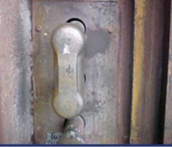
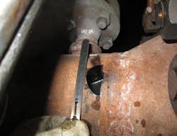
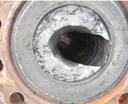
A hole was discovered in 2001 in the El Segundo refinery coker furnace’s rounded return bend, installed in 1995. The photo shows the outside and inside view after removal (Fig. 1).
Furnace fouling
A variety of flame-side and oil-side issues can cause high coker-furnace fouling rates. Flame-side issues involve the burner flame pattern, air-to-fuel ratio, inadequate draft, and convection-section finned tube fouling. If the furnace is balanced draft, there are different potential reliability issues.
Oil-side issues include:
• Oil-flow measurement and control.
• Low oil velocity and inadequate steam velocity to compensate.
• Rapid flow rate and control fluctuations, especially the kind used to online spall.
• Changes in resid quality, especially an increase in contaminants such as sodium, calcium, silicon, molybdenum, iron, FCC catalyst fines, etc. These contaminants can catalyze coking or become part of the furnace-tube coke deposits. Inorganic deposits may be more difficult to remove by online spalling.
Furnace return-bend issues
Return-bend erosion is the most common furnace damage mechanism (Fig. 1).
The critical impingement point is the centerline of the tube into the elbow. Erosion occurs during coke removal. In Chevron installations with a high frequency of coke removal, original rounded return bends took about 7 years to erode all the way throughs` 1 svm,/ . the pipe.
Replacement of rounded return bends with flat-back return bends increased the metal thickness in the critical impingement area (Fig. 2). Doing so doesn’t change the damage mechanism; it just extends the return-bend life before reaching minimum thickness.
If the furnace is a cabin-fired firebox with the return bends in a header box, return-bend inspection can be accomplished when the furnace is out of service without furnace entry. Frequent inspection can track the wall loss and allow planned replacement.
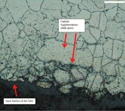
Carburization occurred in thin section of furnace tube (Fig.4).
Furnace-tube wall loss
Wall loss in furnace straight-tube sections has occurred at two different Chevron refineries. While the root cause of this issue is not yet understood, Chevron undertook the following process to identify the issue(s) and possible causes:
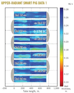
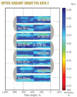
• Ultrasonic spot testing initially identified very isolated tube thinning, which was later followed up with smart pigging for more complete inspection data. Thinning was found in the radiant roof and upper-wall tubes where the process temperature crossed the 800° F. coking threshhold. Tube-skin temperatures in this area are not normally high; the maximum skin temperature is typically in the lower five radiant wall tubes.
• When the thin, upper-radiant tube was replaced, a tube segment was sent to Chevron’s materials lab, where testing identified carburization during normal operation and wall loss during coke removal as the root-cause damage mechanism.
• An independent metallurgical analysis identified sulfidation as the damage mechanism.
Over the course of about the last 4 years, naphthenic acid concentration has increased in both coker units. Resid total acid number (TAN) has not been monitored until recently, with 0.5- 1.0 being the typical blend from high and low-TAN resids. While wall loss in one of the cokers has only been recently detected, the rate of furnace fouling and frequency of coke removal at that unit has increased during the last 4 years.
There is no clear answer as to the root cause of the tube-wall loss problem. As a result, ongoing monitoring and inspection efforts are required. Additional data has been gathered to understand past operation, the rate of change in tube thickness, and if the damage is intermittent or continuous (Figs. 3-6).
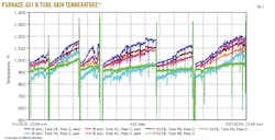
The highest skin temperature (blue) is on the lower radiant wall tube (Fig. 3). The rate of temperature increase has been greater than in the past, which triggers increased furnace-tube coke removal, the step when most of the damage occurs.
Only a very small localized portion of the tube, however, experienced significant wall loss (Fig. 7).
Furnace-tube damage mechanism
The proposed damage mechanisms do not seem to fully explain the furnace-tube damage.
Carburization is a high-temperature mechanism and has been reported at units operating with much higher tube-wall temperatures than Chevron. Also, the location of the most severe damage is the upper radiant wall where skin temperature is considerably lower than near the outlet tubes.
Sulfidation alone does not seem likely for 347H stainless-steel tubes. Resid sulfur is high in the 3-5% range but does not represent a change in operation from historical levels.
Furnace outlet transfer-line piping leaks can occur during or directly after an online spall (Fig. 8).
Naphthenic acid, or TAN, is destroyed by the time the vapor leaves the coke drum. The molecules, however, have survived the vacuum column at about 750° F., which means TAN may not be destroyed until the oil reaches about 800° F. or higher. This situation has occurred in the radiant-roof and upper-wall tubes where wall loss has been experienced.
The damage mechanism could be a combination of all three. Since the mechanism is not understood, an inspection strategy that accounts for the intermittent and nonuniform nature of the wall loss will need to be developed.
Furnace transfer-line issues
Chevron has discovered various furnace outlet transfer-line leaks during or directly after an online spall (Fig. 8). In all cases, the module was bypassed and safely isolated. Operations’ response included removal of resid from other passes as well as opening velocity steam 100%.
One transfer-line leak occurred at the furnace outlet-spool piece during a spall. Quench steam injection added perpendicular to the flow lowered piping temperature from spalling temperature to below 1200° F. The wall loss was due to the impingement on the piping opposite the injection point.
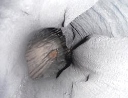
Chevron’s investigation into a separate incident indicated accelerated erosion in a stellite-lined transfer-line bend, accompanied by evidence of coke buildup in the transfer line (Figs. 9a, 9b).
After discovering the leak, inspecting the same location on other passes showed significant wall loss. To remedy this, the quench-steam injection was relocated to the downstream elbow (slightly offset per computational fluid dynamics modeling) to allow injection to be in the direction of process flow. Subsequent inspections indicate this eliminated erosion in this specific area.
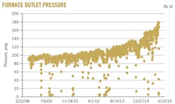
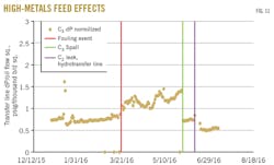
Investigation of a separate incident discovered accelerated erosion in the transfer-line bend, which was lined with stellite (Fig. 9a). Considerable coke buildup in the transfer line led to elevated velocities during spalls (Fig. 9b). The coke was 1.5-in. thick in a 6-in. pipe. Furnace outlet pressure in the transfer line suggests this buildup had occurred over time (Fig. 10). Upon further inspection of individual passes, there appeared to be a step change in fouling while feeding a resid with three-times normal VR calcium concentration (Fig. 11).
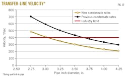
The industry rule of thumb for furnace-tube maximum velocity during online spall to prevent severe erosion had been 400 ft/sec, but companies have lowered this guideline to 350 ft/sec. Trying to apply the same rule to the transfer line is not as straightforward because nonuniform coke accumulation changes the inside diameter and increases velocity (Fig. 12).
The mitigation is to set a limit on transfer-line pressure drop that corresponds to a particular coke thickness. When the limit is reached, the transfer line will be opened, cleaned, and inspected. If the wall loss has been greater than anticipated, the allowable differential pressure (dP) limit may need to be decreased.
Changes
Why have these issues been seen in the last 3-7 years and not previously? There are a few factors:
• The switch to online spalling as the primary furnace-tube coke removal technique has introduced a transfer-line damage mechanism not officially recognized in API 571 Damage Mechanisms. Erosion-corrosion is identified but online spalling is not identified as a routine task that creates erosion.
• Since furnace coking rates have increased, the frequency of online spalling has increased. Inspection programs need to be based on the number of spalls, not just the time interval.
• The rate of coke accumulation in the transfer line has increased at the same time as furnace-tube coking. Analysis of transfer-line coke deposits have shown high concentrations of metals and other contaminants, similar to furnace-tube coke analysis.
The authors
Carolyn Johnson ([email protected]) is a coker process engineer at Chevron Corp. subsidiary Chevron Products Co.’s refinery in Pascagoula, Miss. She holds a BS (2012) in chemical engineering from Purdue University, West Lafayette, Ind.
Dale Wilborn ([email protected]) serves as coker business improvement network leader for Chevron Corp.’s US refining system. Based in El Segundo, Calif., he holds a BS (1980) in chemical engineering from Tulane University in New Orleans.


