P. 3 ~ Continued - Independent recycle valves improve gas compressor turndown ratios

Displaying 3/4
View Article as Single page
This is further accomplished as follows:
• If the flow of Train 1 already equals that of Train 2 (i.e., FI 5134 = FI 5135), both trains' driver speeds are increased in proportion to the available high pressure in the header.
• If FI-5134 > FI-5135, then only the second train (K-2502) speed increases in proportion to the available high pressure in the header.
• If the header pressure (PI-5131) is too low (below normal control point), the control philosophy is reversed, i.e., compressor speed is reduced.
• If the header pressure (PI-5131) equals the control set point, but one train's flow is higher than the other (i.e., FI-5134 > FI-5135), the speed of the lower-flow train is increased and that in the higher-flow train decreased proportionately.
HP control
Control logic is such that when two trains are in operation, the flow is equally distributed between the trains by modulating the turbines' speed and flow-control valve opening to satisfy capacity-control requirements.
The HP stage's bias control system will take both trains' flow signals (FIC-5252A and FIC-5252B) and compare them with the HP header pressure signal provided by PIC-5252. If the header pressure is sufficiently high (i.e., above the normal control set point), the control system generates an output signal to increase and equalize the flow between the two trains.
This is further accomplished as follows:
If the flow of Train 1 already equals that of Train 2 (i.e., FI-5252 A = FI – 5252 B), both trains' driver speeds are increased in proportion to available high pressure in header.
• If FI-5252 A > FI-5252 B, then only the second train's (K-2502) speed increases in proportion to the available high pressure in the header.
• If the header pressure (PI-5252) is too low (below normal control point), the control philosophy is reversed; i.e., compressor speed is reduced.
• If the header pressure equals the control set point, but one train's flow is higher than other (i.e., FI 5252 A > FI 5252 B), the speed of the lower-flow train is increased and that in the higher flow train is decreased proportionately.
Surge protection
Antisurge valves, used to prevent surging during periods of low gas availability (Fig. 1), provide surge protection for the LP and HP compressor stages.
Antisurge control occurs entirely through the control logic of the LP-HP compressor control systems' PLC.
• FV-5154: Train No. 1 LP Compressor Stage.
• FV-5274: Train No. 1 HP Compressor Stage.
• FV-5204: Train No. 2 LP Compressor Stage.
• FV-5314: Train No. 2 HP Compressor Stage.
Individual compressor-stage surge protection occurs automatically, with control logic taking action on individual antisurge valves as needed. If the compressor operating point deviates a few percentage points left from the protection line, the DSH threshold is reached and opens the antisurge control valve (Fig. 2).
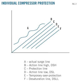
As soon as the operating point returns to the right of the protection line (DSL), it reaches the zone of temporary overprotection. In this zone, two ramps energize to close the controller progressively. The closing sequence of the antisurge valve reaches its end only when the operating point on the right hand side of desaturation (DSLL) line has been reached.
Displaying 3/4
View Article as Single page