Independent recycle valves improve gas compressor turndown ratios
Falah Al-Azmi
Chirag A. Parikh
Kuwait Oil Co.
Ahmadi, Kuwait
| Based on presentation to the 19th Annual GPA GCC Technical Conference, Kuwait, May 4, 2011. |
Installing a recycle valve in parallel with the antisurge valve of a turbine-driven multistage (low pressure/high pressure) centrifugal compressor, in combination with control system modifications, increases the compressor's turndown ratio.
The LP-HP centrifugal compressor for natural gas installed at Kuwait Oil Co.'s gathering center was equipped with an antisurge control valve and control system both to prevent surge and control capacity, limiting the compressor's lower operating range. The lack of alternately required high-pressure or low-pressure gas resulted in frequent opening of the antisurge valve at the compressor's offloading HP stage.
This article describes the field experience of the operating-range limits of running a compressor without a dedicated recycle valve for capacity control and provides guidance on designing and installing an independent recycle control system to increase the lower operating range of a centrifugal compressor.
The actual turndown ratio of the compressor improved from 55% to 20% after an independent recycle valve was installed for capacity control. This improvement allowed the gathering center to operate at lower production rates without gas flaring.
Background
Two main gathering centers at KOC's West Kuwait (WK) fields have a combined production, processing, and export capacity of 430,000 b/d of oil and 160 MMscfd of gas. Four multistage centrifugal gas compressors (two at each gathering center) export gas.
The gathering centers use two identical compressor trains, each containing a two-stage (LP and HP) centrifugal compressor. The two stages are connected to the same shaft and are driven by a single gas turbine powered by fuel gas.
The LP stage of the compressor mainly receives low-pressure gas at around 50 psig from LP separators and discharge from tank vapor compressors. The LP stage increases pressure to around 270 psig and sends gas to the suction end of the high-pressure compressor stage. The HP stage also receives gas from HP separators at the gathering center and increases pressure to around 920 psig.
The LP stage's capacity is 24 MMscfd and the HP stage's 47 MMscfd. The existing configuration of regulating surge and capacity control with an antisurge valve limited the compressor's ability to export gas at lower throughputs due to lack of proper capacity control. The compressor's antisurge control system was detecting compressor surge at lower throughputs and off-loading the compressor by opening the antisurge valve.
The addition of LP and HP compressor recycle valves rectified a flaw in the existing compressor system design, in which the antisurge valves were used for both surge protection and recycle. Adding the new recycle and thermostatic valves, as well as modified antisurge and load sharing programs, required replacing the existing MC5000 compressor controllers with new unit control panels (UCP).
Compressor surge
Surge is a momentary reversal of gas flow in a compressor. Instead of going from the inlet to the discharge, the gas momentarily goes from the discharge backward to the inlet. Surge often produces an audible boom sound and vibrations in the system. Since the gas actually moves opposite to the direction of the rotating impellers, the reversal also produces tremendous stress on the impellers and the shaft. Repeated surge can overheat or even totally destroy the compressor in a short time and presents a serious hazard to personnel working in the area.
Compressor surge occurs when flow is too low with respect to the change of pressure of the compressor or when ΔP is too high with respect to the flow. A decreasing flow coupled with an increasing ∆P, therefore, will quickly result in a surging compressor.
Preventing a compressor from going into surge requires the flow to be increased, the ΔP decreased, or both. Allowing a portion of the gas from the compressor discharge to be recycled to the suction side prevents surge. A surge-control valve, installed at the compressor stage discharge, controls this flow.
Without recycle
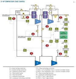
Each compressor train has a programmable logic controller (PLC) in which signals are interfaced with a distributed control system (DCS). LP and HP bias control systems in the DCS control the suction pressure and regulate the flow rates of LP and HP compressor suction, respectively. The compressor's suction pressure signals travel to gas turbine speed control via the bias control system. Speed control compares pressure at the export gas line to modulate suction pressure. Fig. 1 explains the control strategy.

A split range pressure control PIC -5131 with a single set point entered by the operator controls LP suction pressure. PIC-5131 is the remote set point for both FIC-5134 and FIC-5135 compressors. If one of the compressors is running, then the corresponding line would stop affecting the pressure and the other line would handle the control objective but with slower response.
Split-range pressure controller PIC-5252 with a single set point entered by the operator controls HP suction header pressure. PIC-5252 is the remote set point source for both FIC-5255 and FIC-5256 compressors. If one of the compressors is running, then the corresponding line would stop affecting the pressure and the other line would handle the control objective but with slower response.
The HP discharge line pressure is controlled by two pressure controllers: PIC-5612 with a lower set point and PIC-5612 A with a higher set point. (Train 2 controllers are PIC-5622 and PIC-5622 A.)
PY-5612 A (PY-5622 A for Train 2) sends the set point to the K-1502 speed control unit. PY-5612 A selects the lower of PIC-5612 A (PIC-5622 A for Train 2) and FY-5612 (FY-5622 for Train 2) output signals. FY-5612 selects the higher of FIC-5134 (FIC-5135 for Train 2) and PIC-5252 A output signals.
LP control
Control logic operates such that when two trains are in operation, the flow is equally distributed between the trains by modulating the turbines' speed to satisfy capacity control requirements. The LP stage's bias control system will take both trains' flow signals (FIC-5134 and FIC-5135) and compare them with the LP header's pressure signal provided by PIC 5131. If the header pressure is sufficiently high (i.e., above normal control set point, 52.5 psig), the control system generates an output signal to increase and equalize the flow between the two trains.
This is further accomplished as follows:
• If the flow of Train 1 already equals that of Train 2 (i.e., FI 5134 = FI 5135), both trains' driver speeds are increased in proportion to the available high pressure in the header.
• If FI-5134 > FI-5135, then only the second train (K-2502) speed increases in proportion to the available high pressure in the header.
• If the header pressure (PI-5131) is too low (below normal control point), the control philosophy is reversed, i.e., compressor speed is reduced.
• If the header pressure (PI-5131) equals the control set point, but one train's flow is higher than the other (i.e., FI-5134 > FI-5135), the speed of the lower-flow train is increased and that in the higher-flow train decreased proportionately.
HP control
Control logic is such that when two trains are in operation, the flow is equally distributed between the trains by modulating the turbines' speed and flow-control valve opening to satisfy capacity-control requirements.
The HP stage's bias control system will take both trains' flow signals (FIC-5252A and FIC-5252B) and compare them with the HP header pressure signal provided by PIC-5252. If the header pressure is sufficiently high (i.e., above the normal control set point), the control system generates an output signal to increase and equalize the flow between the two trains.
This is further accomplished as follows:
If the flow of Train 1 already equals that of Train 2 (i.e., FI-5252 A = FI – 5252 B), both trains' driver speeds are increased in proportion to available high pressure in header.
• If FI-5252 A > FI-5252 B, then only the second train's (K-2502) speed increases in proportion to the available high pressure in the header.
• If the header pressure (PI-5252) is too low (below normal control point), the control philosophy is reversed; i.e., compressor speed is reduced.
• If the header pressure equals the control set point, but one train's flow is higher than other (i.e., FI 5252 A > FI 5252 B), the speed of the lower-flow train is increased and that in the higher flow train is decreased proportionately.
Surge protection
Antisurge valves, used to prevent surging during periods of low gas availability (Fig. 1), provide surge protection for the LP and HP compressor stages.
Antisurge control occurs entirely through the control logic of the LP-HP compressor control systems' PLC.
• FV-5154: Train No. 1 LP Compressor Stage.
• FV-5274: Train No. 1 HP Compressor Stage.
• FV-5204: Train No. 2 LP Compressor Stage.
• FV-5314: Train No. 2 HP Compressor Stage.
Individual compressor-stage surge protection occurs automatically, with control logic taking action on individual antisurge valves as needed. If the compressor operating point deviates a few percentage points left from the protection line, the DSH threshold is reached and opens the antisurge control valve (Fig. 2).
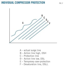
As soon as the operating point returns to the right of the protection line (DSL), it reaches the zone of temporary overprotection. In this zone, two ramps energize to close the controller progressively. The closing sequence of the antisurge valve reaches its end only when the operating point on the right hand side of desaturation (DSLL) line has been reached.
Limitations, capabilities
The compressor control logic described thus far can operate both compressors in parallel with necessary control of suction and discharge pressure and flow for both LP and HP stages when it operates at 55% capacity or more. The control logic equally distributes flow between trains by modulating turbine speeds when two trains are in operation. It also prevents any surge condition in LP or HP stages by opening the appropriate antisurge valve for low gas flow.
The limitations of this control system, however, come into play when it must balance the varying flow requirements between two stages (LP and HP) of each compressor. Attempting to do so limited the compressor's turndown ratio to 55%, as one stage would reach surge limit and off-load at lower gas flow rates.
With recycle
New LP and HP compressor-stage recycle valves entered service to rectify the flaw in the existing compressor system design as a result of which antisurge valves were used for both surge protection and recycle.
• FV-7223: Train No. 1 LP Compressor Stage.
• FV-7224: Train No. 1 HP Compressor Stage.
• FV-7221: Train No. 2 LP Compressor Stage.
• FV-7222: Train No. 2 HP Compressor Stage.
The new recycle valves operate in parallel with the existing antisurge control valves and are controlled through the LP-HP compressor control system's PLC.
Recycle control is independent of the normal LP-HP compressor bias control described earlier, acting in a support role to stabilize the compressor operation. In its simplest form, recycle control is a means of balancing flows between the LP and HP compression stages of each train.
Recycle control
Per the existing compressor bias control (Fig. 1), a higher selector compares signals coming from the LP compressor-stage suction flow controller FIC-5134 and HP compressor-stage suction flow controller FIC-5255 A. The signal of the maximum value between FIC-5134 and FIC- 5255 A travels via FY-5612 A to gas turbine KT-1500 combustors and adjusts speed to accommodate the highest flow demand, allowing adjustment of flow to the LP or HP sections of the compressor but not satisfying the flow demand of both sections of the compressor. Instead, one of the compressor stages will have to use its new recycle valve.
When FIC-5134 signal is lower than FIC-5255 A, for example, the control logic sends a signal to LP compressor-stage recycle valve FV-7223, forcing it open. When, conversely, FIC-5134 signal is higher than FIC-5255 A, the control logic sends a signal to recycle valve FV-7224, forcing it open.
Observations
Installation of an additional recycle valve at each stage of the compressor has given flexibility to balance the varying flow requirements at each stage and improve the turndown ratio of the compressor from 55% to 20%, facilitating continuous smooth gathering center operations at lower production rates. The dedicated recycle valves have also prevented frequent offloads of compressors at lower throughputs, resulting in reduced gas flaring.
The authors


More Oil & Gas Journal Current Issue Articles
More Oil & Gas Journal Archives Issue Articles
View Oil and Gas Articles on PennEnergy.com