P. 2 ~ Continued - Independent recycle valves improve gas compressor turndown ratios
Displaying 2/4
View Article as Single page
Compressor surge occurs when flow is too low with respect to the change of pressure of the compressor or when ΔP is too high with respect to the flow. A decreasing flow coupled with an increasing ∆P, therefore, will quickly result in a surging compressor.
Preventing a compressor from going into surge requires the flow to be increased, the ΔP decreased, or both. Allowing a portion of the gas from the compressor discharge to be recycled to the suction side prevents surge. A surge-control valve, installed at the compressor stage discharge, controls this flow.
Without recycle
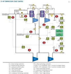
Each compressor train has a programmable logic controller (PLC) in which signals are interfaced with a distributed control system (DCS). LP and HP bias control systems in the DCS control the suction pressure and regulate the flow rates of LP and HP compressor suction, respectively. The compressor's suction pressure signals travel to gas turbine speed control via the bias control system. Speed control compares pressure at the export gas line to modulate suction pressure. Fig. 1 explains the control strategy.

A split range pressure control PIC -5131 with a single set point entered by the operator controls LP suction pressure. PIC-5131 is the remote set point for both FIC-5134 and FIC-5135 compressors. If one of the compressors is running, then the corresponding line would stop affecting the pressure and the other line would handle the control objective but with slower response.
Split-range pressure controller PIC-5252 with a single set point entered by the operator controls HP suction header pressure. PIC-5252 is the remote set point source for both FIC-5255 and FIC-5256 compressors. If one of the compressors is running, then the corresponding line would stop affecting the pressure and the other line would handle the control objective but with slower response.
The HP discharge line pressure is controlled by two pressure controllers: PIC-5612 with a lower set point and PIC-5612 A with a higher set point. (Train 2 controllers are PIC-5622 and PIC-5622 A.)
PY-5612 A (PY-5622 A for Train 2) sends the set point to the K-1502 speed control unit. PY-5612 A selects the lower of PIC-5612 A (PIC-5622 A for Train 2) and FY-5612 (FY-5622 for Train 2) output signals. FY-5612 selects the higher of FIC-5134 (FIC-5135 for Train 2) and PIC-5252 A output signals.
LP control
Control logic operates such that when two trains are in operation, the flow is equally distributed between the trains by modulating the turbines' speed to satisfy capacity control requirements. The LP stage's bias control system will take both trains' flow signals (FIC-5134 and FIC-5135) and compare them with the LP header's pressure signal provided by PIC 5131. If the header pressure is sufficiently high (i.e., above normal control set point, 52.5 psig), the control system generates an output signal to increase and equalize the flow between the two trains.
Displaying 2/4
View Article as Single page