Special Report: Crude Export Riser— Conclusion: Pipeline design allows continued use beyond field’s life
The export pipeline system includes two modules permitting future connections and another serving as a contingency for the freestanding hybrid riser (FSHR), making the infrastructure flexible enough to be used in its full capacity after the original field is depleted. A pipeline end termination (PLET) begins the line, which is connected to the FSHR base by a rigid-base jumper (RBJ). The line splits in four major sections to allow for subsea equipment installation and is terminated by a by-pass pipeline end manifold (PLEM), directing the flow to an FSO prior to PRA-1 commissioning and redirecting it afterwards.
The first article in this three-part series described the FSHR in detail before examining its design and installed responses (OGJ, Nov. 10, 2008, p. 58). The second article detailed FSHR installation and monitoring (OGJ, Nov. 17, 2008, p. 56), with this concluding article discussing its integration with the export pipeline.
Design basis
Designed under DNV OS-F101 2000 and in accordance to API 5L 2000 for a life in service of 25 years, the 18-in. pipeline can sustain internal and external pressure, as well as local buckling and collapse, to a depth of 1,800 m. WT measures 0.688, 0.750, 0.875, 1.000, and 1.125 in. at various points along the pipeline. Corrosion protection and thermal insulation consist of a triple-layer FBE-adhesive-solid poluypropylene (SPP) and an additional 2-in. SPP to achieve an overall heat transfer coefficient of 5.2 W/sq m K. A 2-in. thick polyurethane layer over primer coats all field joints.
Temperature proved to be a major design driver due to the thermo-buckling effect which causes lateral buckling and pipeline walking. Table 1 shows operating data.
Three in-line structures placed along the pipeline between P-52 and PRA-1 provide contingency relief.
- PLEM Y, to make a direct connection from P-52 to the pipeline through a flexible riser.
- Rigid jumper, providing an additional entrance to allow future development.
- PLEM T, for use as an entrance flow for future pipeline installations.
Analysis, design
Pipeline analysis and design requires definition of the route, including soil and stability evaluations, to find the best route for keeping risks minimal while also reducing constraints on the lay vessel’s capabilities. Petrobras chose the general route used to avoid both natural obstacles and existing or to-be-installed Roncador subsea structures. Route optimization focused on minimizing material and resource use through assessment of free spans, on-bottom stability, crossings, and slope. Results showed minimum curve radius and other installation restrictions to be met by the pipelay vessel.
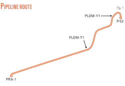
Fig. 1 shows the pipeline route. Project engineering addressed stability of both equipment and pipeline, taking estimated friction coefficients into account to evaluate risks and optimize routing. Bottom roughness analysis showed 21 free spans requiring remediation; 5 with mechanical supports and 16 with grout bags. Sensitivity analysis on design parameters along the pipeline route included uncertainties regarding soil parameters and lay conditions along different paths inside the pipeline corridor. Results showed a greater number of free span corrections for any of the other possible routes, concluding the selected route was the best option.
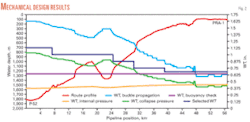
WT calculations accounted for internal pressure and potential collapse, checking results for buckling propagation. Local buckling limits determined the maximum bending moments and strains to which the pipe could be subjected. Selected thicknesses address internal pressure and collapse, but not buckle propagation, making buckle arrestors mandatory.
Fig. 2 shows mechanical design and route profile.
Thermomechanical analysis
High temperature-high pressure pipelines may face high loads-strains due to the thermomechanical behavior. Moreover, issues like end expansion, thermal cycle fatigue, ratcheting, and longitudinal walking, among others, can cause severe damage to the entire flow system if it is not properly designed.
Soil-pipeline interaction, pipeline expansion, maximum stresses and strains, girth-weld fatigue, pipeline axial-lateral ratcheting, free-span assessment, buckling initiation, pipeline crossings, and FEA model details provide the primary bases for describing methods and parameters required for expansion design.
Deep water and soil conditions often make methods such as burial or rock dumping impractical or overly expensive. More equipment on the line makes it more difficult to design for thermal expansion. Three design goals therefore become paramount:
- Large axial (longitudinal) end deflection.
- Global lateral buckling and fatigue.
- Axial-lateral ratcheting.
Excessive axial-lateral distortion of the line can cause severe damage. As the ends are allowed to expand, axial soil resistance builds toward the middle of the line until lateral buckling occurs. If this phenomenon remains uncontrolled, local buckling may result and even plastic collapse of the cross section or fatigue failure at girth welds become possible due to cyclic thermal loading.
Planning to initiate global buckling at certain points of the pipeline can reduce stress-strain and avoid undesired effects. Installing buoyancy sections and sleepers (short pipes to provide vertical upsets) can reduce lateral resistance between the pipe and the soil, effective in reducing buckling curvatures and stress ranges across a number of heating and cooling cycles.
P-52 oil export pipeline runs at a high temperature gradient of up to 70° C. as well as cyclic thermal loads due to planned oil-flow shutdowns. A complete FEA assessment of lateral buckling, ratcheting, and walking showed the need to use lateral buckling mitigation to avoid these problems. Both sleepers and buoyancy modules were chosen to overcome lateral buckling effects and a suction pile at P-52 location controls pipeline walking.
Finite-element software ABAQUS constructed a full three-dimensional model of the pipeline. The model includes seabed terrain effects and several operational heating and cooling cycles. In-line structures, jumpers, pipeline crossings, and lower and upper-bound soil properties were included in the model to best describe the system. Because the entire 56-km pipeline with all boundary conditions proved unmanageable for a single detailed FEA run, we split it into four segments long enough to be manageable and still correctly represent global behavior.
Buckle initiation and mitigation applied along the route (across each of the four segments) absorb midline thermal expansion in a controllable manner by applying buoyancy modules and dual sleepers at discrete locations to work as planned points for global buckle initiation. Detailed FEA assessed midline expansion in global buckles, whether planned or unplanned, and determined if project requirements were met.
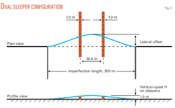
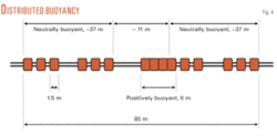
The first approach used standard single sleepers, but these did not meet fatigue acceptance criteria due to in-line and cross-flow vortex-induced vibration effects. The dual sleeper configuration met acceptance criteria (Fig. 3). The pipes are about 30-m long with a vertical upset of about 1 m. Ten dual sleeper sets previously laid and six distributed buoyancy sections (Fig. 4) are the mitigation devices. The distributed buoyancy makes the line almost neutral buoyant; reducing lateral friction and permitting lateral buckle initiation.
Pipeline walking
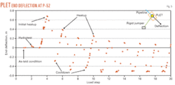
Pipeline walking also needs to be mitigated. Cyclical thermal loads from shutdowns and start-ups of the system tend to displace the PLET at the FSHR base from its original position. The PLET would displace about 2 m (retraction) along the pipeline axis if no control device were present in the soft-soil condition (more conservative). The same 5-m OD, 17-m long suction pile installed for pipeline lay initiation limits pipeline end displacement to about 0.5 m.
Fig. 5 shows PLET displacements. Walking direction is from the hot end (P-52) towards the first buckle location.
Pipeline installation
The J-lay method’s ability to manage large loads, in this case due to a combination of water depth and pipe weight, led it to be chosen for pipeline installation. The method positions prefabricated 48-m quad joints of pipe into the J-lay tower where they are welded to another quad joint before the 96-m assembled pipe length is deployed into the sea. The process results in a free-hanging catenary from seafloor to the vessel.
The hang-off module supports the pipeline during J-lay operations and is the final attachment point before the line moves into free-catenary suspension. Vessel crew can move the module fore and aft, adding the flexibility needed to deploy such structures as in-line bases.
Pipelay took place with the line empty from 1,800 m to about 760 m. Stability issues prompted a flooded lay from 760 m to 100 m. Shallower depths required adjustments to the J-lay tower angle to avoid excessive loads potentially hazardous to the pipeline. Angles varied from 83° to 61º.
PLEM, base
Petrobras first considered connecting any equipment along the pipeline (PLEM Y, rigid jumper, and PLEM T) to the line with rigid-base jumpers to deal with thermal expansion. This approach, however, required thermomechanical analysis results at an early stage of design; leading to potentially complex geometry and RBJs too heavy for the installation vessels. This alternative’s large number of connections also posed a potential leak problem. Adopting in-line structures helped overcome these problems by allowing equipment design and thermomechanical analysis to be performed in parallel.
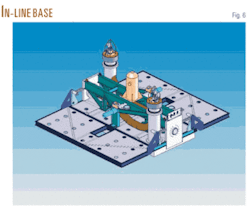
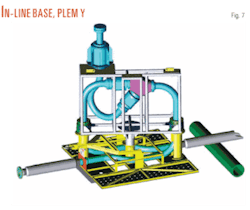
Fig. 6 shows an in-line base (ILB) composed of piping, two mandrels, and a guiding system for the valve module connection, installed after deployment of the ILB. The PLEM Y (Fig. 7), rigid jumper, and PLEM T have the same ILB structure, allowing interchangeability and simplifying design and installation.
ILB installation involved positioning the structure on the J-lay tower, aligned to the pipe end of the catenary supported by the hang-off module. Welding the pipeline to the ILB preceded lowering the assembly into the water and welding another quad joint to its upper end, continuing the J-lay process.


