Golfinho route optimization keys successful lay off Brazil
Marcelo José Barbosa Teixeira, Claudio Roberto Mansur Barros, Mônica de Castro Genaio; Petróleo Brasileiro SA, Rio de Janeiro
Carlos Terêncio Pires Bomfimsilva, Janaina de Figueiredo Loureiro, Vivianne Cardoso Pessoa Guedes; Intec Engineering, Rio de Janeiro
The export gas pipeline from the Espírito Santo basin’s deepwater Golfinho field off Brazil required extensive geophysical and oceanographic work before beginning pipeline design, it being the first development in the basin.
The geophysical survey showed that the critical area along the pipeline route lay on the shelf break and in deep water (100-350 m). Canyons, ravines, and scarps forced pipelaying in the area to proceed with the lowest values of tension possible, in order to minimize residual tension along the pipe. Such features also required that free spans remain under the established limits for pipe stress and spans length.
Golfinho will produce 100,000 b/d of light oil through a floating production, storage, and off-loading vessel moored in water 1,350 m deep. A 12-in. steel pipeline, fitted with a pipeline end terminal (PLET) at the deep end of the line to allow subsea connection of the flexible riser, will export associated gas to an onshore processing unit in Cacimbas.
Subsea 7 reel-lay vessel Skandi Navica performed the deepwater and most of the shallow-water installation. Petrobras S-lay barge BGL-1, completed the remaining shallow water installation, including the shore approach.
Operator Petróleo Brasileiro SA contracted Intec Engineering to design the pipeline, including structural analysis and route optimization, but managed the field survey itself. This article describes each of these activities.
Survey
The geophysical and oceanographic survey started with the first proposed pipeline route. Onboard evaluation of the data showed that the continental slope of the area had extremely complex near-surface geology, characterized by canyons and ravines, and gradients of up to 60° at the shelf break. This prompted a semi-regional scale high-resolution geophysical, geological, and geotechnical survey, aimed at identifying natural and man-made obstacles that could pose a risk to the structural integrity of the pipeline. The survey also sought an understanding of the geological and oceanographic factors responsible for the features observed on the seafloor.
The survey, conducted between April and October 2004, captured more than 470 sq km of data, limited by the 60 m and 1,380-m isobaths (outer continental shelf and medium slope). It used single-beam bathymetry for seafloor morphology investigation, side-scan sonar with 100% coverage for superficial sediment distribution evaluation, and a 3.5-khz subbottom profiler for the investigation of subsurface structures.
A subsequent geological and geotechnical sampling campaign used a 6-m long piston-corer, with coring locations based on the geophysical records. Dating of selected samples used biostratigraphic methods.
The integrated interpretation of all geophysical and geological data allowed identification of areas of the seafloor to be avoided in route design, such as high slopes and areas dominated by erosion. Understanding the geological history of the area led to a qualitative slope stability evaluation as a function of the geological environment.
The selected route corridor considered all aspects that could present risk to the pipeline integrity, restricting more detailed and time-consuming geotechnical investigation to the final corridor and thereby considerably reducing the final budget of the survey.
Acquisition of oceanographic data included deployment of two mooring lines along the pipeline route during a 1-year period; one in water 300 m deep and the other at 1,300 m. Mooring line equipment included an acoustic current profiler for the top 100 m and current meters with conductivity-temperature-depth recorders distributed along the line. Deploying the lowest current meter 5.3 m from the seabed quantified bottom currents.
Data acquisition for the shore-approach area consisted of simultaneous measurement of directional waves and current profiles, carried out with an acoustic current profiler with wave-processing capacity deployed 20 m deep. Beach profiles and sediment grain distribution provided data for numerical simulation of beach-seabed profile evolution and support pipeline burial specifications.
Structural design
Structural design focused on material and corrosion assessment, WT, and pipelay feasibility.
Pipeline specifications called for seamless pipe with a minimum yield stress of 415 MPa. Material and corrosion assessment checked the suitability of carbon-manganese steel pipe for conveying gas containing 0.56% CO2 at a maximum pressure and temperature of 230 kg/sq cm and 50º C. at the PLET in a potentially wet environment.
Corrosion rate estimates followed the De Waard and Milliams prediction model along the entire pipeline, considering CO2 partial pressure, operating-temperature profile, operating-pressure profile, and pH values. Design also considered the effects of 95% efficient corrosion inhibitors as a means of limiting corrosion.
Design dictated a total corrosion allowance of 3 mm for water from 850 m to 1,200-m deep and 1.6 mm for shallower water.
Consideration of three failure modes determined the pipeline’s required WT: burst pressure, buckling due to combined bending and hydrostatic pressure, and buckle propagation. DNV OS F-101 provided the basis for these assessments.1 These failure modes, when checked across the pipeline phases (pipelay, hydrotesting, and operation), resulted in the following load cases:
• Pressure containment during operation.
• Pressure containment during hydrotesting.
• Local buckling due to combined bending and external pressure during installation.
• Local buckling due to combined bending and external pressure during depressurization.
• Buckle propagation during installation.
• Buckle propagation during depressurization.
Reel-lay installation does not allow for concrete coating, requiring that the WT of the pipe also provide sufficient weight to ensure onbottom stability, particularly in shallow waters. The reel-lay method also requires the pipe to be designed with sufficient WT for spooling onto the reel without achieving critical strain. In this case, the minimum nominal pipe wall to comply with the critical strain criterion was 15.9 mm (0.625 in.).
Pipeline operation in water less than 100 m deep, where closeness to the coast might imply a higher level of human activity, required adoption of a high safety class. Normal safety class applied to the operation phase of the rest of the pipeline. Installation and hydrotesting phases specified a low safety class for the entire pipeline.
External hydrostatic pressure primarily governs WT for deepwater applications.
Pipelaying poses the most critical challenge to line pipe, due to the potentially high bending load brought about by any shift in the surface positioning of the pipelay vessel. If the pipe is designed with a wall thin enough to lay readily but still sufficient to resist the combined hydrostatic pressure and bending, and an unexpected buckle forms, it will propagate until a lower hydrostatic pressure is reached, potentially damaging a large section of the pipeline.
Avoiding this situation typically results in the adoption of either of two design strategies: selecting a thicker wall to resist buckle propagation; or welding buckle arresting collars at selected spacing along the pipeline, preventing the buckle from propagating beyond the buckle arrestors.
The reel-lay method typically dictates use of as thick a wall as possible, since it would be impractical to spool buckle arrestor collars onto the reel. The alternative to this, welding the collars at the ramp, would jeopardize pipelaying speed. Even using clamped buckle arrestors would require frequent interruptions for collar assembly.
Conversely, during J-lay installation, a collar supports the whole length of pipeline suspended from the vessel, making buckle arrestors easily useable.
The Golfinho export line faces the additional requirement of resisting buckle propagation at the end of its lifetime-i.e., after corrosion allowance is reached-so that pipeline damage due to potential local buckling would not propagate if the pipeline is depressurized in the operational phase. Fig. 1 presents the required WT to resist propagation.
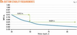
The step at 850 m for the depressurization condition relates to the change in corrosion allowance. Using 20.6 mm (0.812-in.) WT for pipe in water deeper than 100 m and located on a rough seabed will improve free span capability.
Using an 80º pipelay ramp in water 1,200 m deep requires top tension of 1,472 kN to lay 12-in. pipeline with 25.4 mm (1-in.) WT.
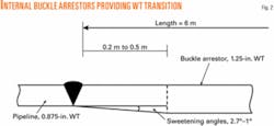
Minimizing top tension during pipelay in deep water saw a conceptual design for internal buckle arrestors initiated. A 22.2 mm (0.875-in.) WT pipe can resist buckle propagation during installation. But Golfinho requires a 12-in. pipe with a thicker wall to be butt-welded to the pipeline at a given spacing as a buckle arrestor. The resulting 31.8 mm (1.25-in.) WT stands in accordance with DNV OS-F101 recommendations.
Welding internal buckle arrestors inside the stalks in preparation for spooling would avoid reducing pipelay speed. The change in pipe stiffness created by the internal buckle arrestor, however, may create an excessive compressive strain in the thinner pipe close to the weld area, increasing the risk of local buckling during spooling.
In order to maintain proper design, a transition section needs to be machined at the arrestor edges. The arrestor does not need to be short, and a 6-m long pipe could allow sweetening angles more favorable for the transition sections (Fig. 2).
The pipeline could accommodate internal buckling arrestors in the deepwater section, given spacing of 48 m. The reduction on top tension force would reach 12% under these conditions, compared to the constant 25.4 mm (1-in.) WT designed for buckle-propagation criterion at end-of-lifetime.
Since the Skandi Navica applied a pipelay ramp steeper than 80° at the deepwater end of the Golfinho pipeline and considering that designing the internal buckle arrestor would have required experimental laboratory testing to ensure resistance to spooling without buckling, a buckle arrestor was not used for this project.
The pipeline route, however, traverses shallow water for about 50 of its 67 km, where WT is governed by onbottom stability (Fig. 3).
The commercial finite-element software, Offpipe, assessed installation feasibility. The analysis performed stress-level checks along the pipe related to the pipelay geometry for the range of the project water depths.
The following factors affect selection of pipelay ramp angle:
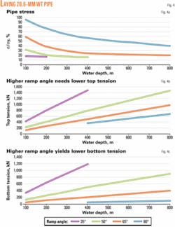
• Bottom tension is relevant for the incidence and size of free spans, and high ramp angles will result in lower bottom tension, allowing for free-span optimization.
A higher ramp angle also requires lower top tension, essential in deep water to keep the required top tension within the vessel capacity.
• The stress levels observed at the sagbend region, mainly in shallow water, however, limit higher ramp angles.
Fig. 4 shows the pipe stresses, the top tension, and the bottom tension along the pipeline route, for water from 100 m to 800 m deep, applying 35°, 50°, 65°, and 80° ramp angles related to the horizontal, using 20.6-mm WT pipe.
Route optimization
Sediment distribution, subsurface structures, and evolution of geotechnical seafloor conditions defined the pipelay route corridor and established a base-case route.
Assessing alternative routes in the anticipated rough regions with the seabed features observed in the produced geophysical maps allowed for optimization of the pipeline route.2 3
Because the allowable free-span length needs to be determined first, the incidence of potential free spans may be estimated when assessing alternative routes.
DNV RP F105 recommendations determined allowable free span, using first-pass screening criteria for cross-flow analysis and fatigue evaluation to check pipe integrity for in-line vibration.4 Allowable free spans were also checked for ultimate limit-state criteria.
A single span with leveled shoulders determined the natural frequency of the pipeline regarding soil stiffness and effective axial force.
The soil along the pipeline route varied from soft clay in water 1,200 m deep to dense sand at 60 m. The higher difference between ambient and operational temperatures increased effective tension on the pipeline in deep water.
Fatigue analysis considered both the current acting perpendicular to the pipeline and its velocity, following the Weibull cumulative distribution function fitted to the available current data. This assessment used the proposed fatigue curve F3 for seamless pipe from DNV RP C203.5
In the pipeline section deeper than 850 m, where effective compressive forces were higher, free spans were limited to 11 m. For the remaining nonconcrete coated sections, the allowable free span increased to 22 m. The concrete-coated shallow-water section of the pipeline had free spans limited to 15 m.
This fatigue analysis considered only current perpendicular to the pipe, leading to conservative results. Local oceanographic information can produce a better scatter diagram.
Route optimization requires several steps, from studying the bathymetry and side-scan sonar maps2 3 to distinguishing rough seabed circumstances along the route corridor that might require alternative routes. Optimization next requires the minimum bend radius be established for areas where changes in route direction are anticipated, taking into consideration soil friction and residual tension within the pipeline.
Preparation to the free-span analysis also requires that the pipe embedment in clay soils be estimated. Finally, the free-span assessment simulates the pipeline sited on rough seabed along the alternative routes.
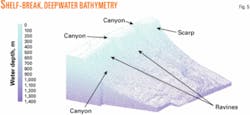
Few potential free spans were anticipated on the continental shelf, characterized by a regular bathymetry and water up to 100 m deep. On the shelf break and in the deepwater region (100-800 m), however, a much rougher seabed characterizes the bathymetry, with scarps, ravines, and canyons all present (Fig. 5). These conditions require a careful search for the optimized route.
Fine soil, silt, and clay, characterize the deepwater seabed, with the expected embedment increasing with water depth and reaching 50% of OD in 1,200 m of water.
Offpipe estimated the incidence and main characteristics of any free-spans along the pipeline for potential alternative routes.
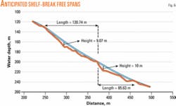
The base-case pipeline route showed potential for 198 spans higher than 1 m in deep water, the most critical being in the shelf break, where spans up to 120-m long and 10-m high were anticipated (Fig. 6).
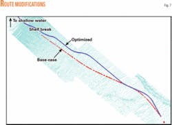
Adjustments in the base-case route aimed to reduce the incidence of free spans. Modifications affected the route between 130 m and 800 m of water, with the highest concentration of canyons and ravines (Fig. 7).
Tables 1 and 2 present the characteristics of the maximum free span identified in the optimized route, and as the free span with the maximum pipe stress, respectively.
These characteristics reflect the maximum residual tension of 150 kN along the pipeline in the shelf break, the recommended value for water between 100 and 350 m deep. Higher residual tensions would promote longer and higher free spans, which might exceed the allowable pipe stress and free-span length limits.
The optimized route included only 19 free spans higher than 1 m, with none expected to exceed 3 m.
Acknowledgments
The authors thank Petrobras’s pipeline design and marine installation group for their work during the geophysical and oceanographic survey and for their comments and suggestions presented during the preparation of this paper. ✦
References
1. DNV OS F-101, “Submarine Pipeline Systems, Amendments April 2004,” Det Norske Veritas, January 2000.
2. DE-3671.00-6521-932-PPR-001-Rev.A, Golfinho field bathymetry map.
3. DE-3671.00-6521-932-PPR-002-Rev.A, Side-scan sonar map.
4. DNV RP F-105, “Free Spanning Pipelines,” Det Norske Veritas, March 2002.
5. DNV RP C-203, “Fatigue Strength Analysis of Offshore Steel Structures,” Det Norske Veritas, October 2001.
Based on presentation to the Deep Offshore Technology conference, Vitória, Brazil, Nov. 8-10, 2005.
The authors
Marcelo José Barbosa Teixeira (marcelojbt@ petrobras.com.br) has been manager of Petrobras engineering department’s pipeline design and marine installations group since September 2002. He received a degree in mechanical engineering (1975) from Universidade Federal de Pernambuco, Brazil, and has worked as a subsea petroleum engineer since 1977.
Claudio Roberto Mansur Barros has worked at Petrobras since 2001 in the design and installation of subsea pipelines. He received a degree in mechanical engineering (1994) from Universidade Federal Rio de Janeiro and a masters degree in metallurgical engineering (1996) from Universidade Federal Fluminense, Brazil.
Mônica de Castro Genaio has worked in the design and installation of subsea pipeline at Petrobras since 2003. She holds a degree in mechanical engineering (1998) from Universidade do Estado do Rio de Janeiro and is currently working towards her masters degree in subsea engineering at the Universidade Federal Rio de Janeiro.
Carlos Terêncio Pires Bomfimsilva is engineering manager at Intec’s Rio de Janeiro office in charge of pipeline and subsea systems development design. He received a degree in mechanical engineering (1986) from Universidade Federal Fluminense, Brazil, and a masters degree in subsea engineering (2004) from Heriot-Watt University, Edinburgh, UK.
Janaina de Figueiredo Loureiro is pipeline engineer for offshore projects at Intec’s Rio de Janeiro office. She received a degree in chemical engineering (1997) from Universidade do Estado do Rio de Janeiro and a masters degree in subsea engineering (2001) from Universidade Federal Rio de Janeiro.
Vivianne Cardoso Pessoa Guedes is project engineer for pipeline and subsea systems development design at Intec’s Rio de Janeiro office. She holds a civil engineering degree (2002) from Universidade de Brasília and a masters degree in geotechnical engineering (2004) from Universidade Federal Rio de Janeiro.


