Flexible steel pipe solves Canadian rehabilitation
When deterioration of existing pipes precludes cost-effective traditional repair, slip-lining the old pipe with flexible steel pipe provides a ready alternative. The flexible steel pipe contains the pressure, making the structural condition of the pre-existing steel pipe unimportant.
Rehabilitation application of flexible steel pipe typically results in significant cost savings, minimal environmental disruption, and elimination of the need for new pipeline permits. Field sweeps of about 90° are generally acceptable in rehabilitation lines. Elbows are cut out because their bends of radius are too narrow for flexible pipes.
This article examines a specific field application of flexible steel pipe, the conditions governing pull-through application, and the general design, standards, and qualification of flexible steel pipe.
Field application
Rehabilitation of a 2 km, 6-in., Canadian pipeline recently specified flexible steel pipe. Corrosion problems had shut down the traditional steel pipeline. The rehabilitation focused on conveying liquid carbon dioxide to an injection well for enhanced oil recovery.
The existing pipeline’s route included five or six landowners, making it extremely difficult to get approvals for a new pipeline. The ability to make one single pull, avoiding property disruption and easement-access issues along the route, was a key benefit to the pipeline owner.
The route between the wellhead and battery included two 90° turns and a road crossing.
The welded flexible steel end fittings fit into the 6-in. steel pipe and maneuvered the winding pipeline route, making it possible to complete the 2-km pull with no midline bell holes.
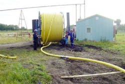
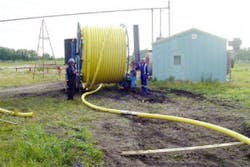
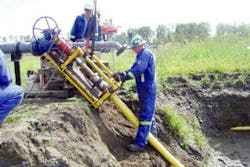
Fig. 1 depicts the flexible steel pipe reel pulled into position for payoff and entry into the existing steel pipeline. Also visible is the midline welded connection with the low-profile end fittings.
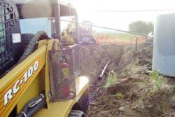
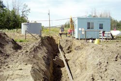
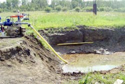
Fig. 2 shows the opposite end of the existing pipeline being readied for the pull-through operation. The flexible steel pipe exits the pre-existing steel pipe in Fig. 3, with the pull-in end fittings being cut off and a fitting with an ASME flange being swaged into place in Fig. 4. Fig. 5 shows the completed pipeline.
Actual pipe installation (less site preparation) took 2 days and could have taken 1 day if not for equipment problems.
Similar rehabilitation of gathering lines with flexible steel pipe would enjoy much the same benefits as those detailed here.
Pull-through applications
Pipe pull-through applications begin with preparation of the existing pipeline for installation of the flexible pipe. Clearing the pipeline, generally with several types of pigs, and cutting out obstacles such as elbows accomplishes this preparation.
Passing a gauge pig with an appropriately scaled aluminum gauge plate or a dummy end fitting with or without an attached short pipe verifies that the line is clear of obstructions. Required tension is typically about 1 tonne/km of straight pipe for 3 in., 1,500-psi or 4 in., 1,000-psi pipe, and 40% more for 4 in., 1,500-psi pipe. Field sweeps can add roughly 40% tension per 90° bend.
A pig pulls a wire rope line through the pipeline once it is prepared, or a steel pipe or rod is assembled and passed through it. Attaching the rod to the flexible steel pipe and pulling it back draw the flexible pipe through the old pipeline. Attaching the pipe to the fixture with a breakaway link limits tension. Applying a lubricant to the pipe eases its passage.
Layers, materials
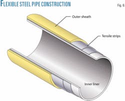
Flexible steel pipe has four layers (Fig. 6). The innermost layer, an extruded thermoplastic tube, seals in the conveyed fluid. Most liners use pipe-grade polyethylene, but carbon-filled PE can be used to meet antistatic requirements.
Two contra-wound layers of carbon steel strip reinforcements wrap in a spiral on top of the liner at a roughly 55° lay angle. The steel strips resist internal pressure and tensile loads on the pipe. The steel layers are not exposed to the bore fluid, lying in a considerably milder environment in the annulus between the inner and outer extruded layers.
The outermost layer, a thick extruded external shield, protects the underlying layers of the pipe from the external environment. The standard version of this outer shield uses yellow pipe-grade PE, formulated with a package of colorants, stabilizers, and antioxidants designed for up to 3 years of outdoor exposure.
Optional black carbon-filled PE resists long-term UV exposure well and can drain external static charges, but has high emissivity that leads to significant heating during the day and cooling at night.
A white PE outer shield is preferred for applications in high-intensity UV light.
Design range
Table 1 shows standard flexible steel pipe designs. Most of the nominal pressure ratings match ANSI classes for compatibility with other components, such as valves and flanges. ANSI Class 300 corresponds roughly to 5.15 MPa (750 psi), Class 400 to 6.89 MPa (1,000 psi), and Class 600 to 10.3 MPa (1,500 psi).
Standards
American Petroleum Institute standards API 17J, 17K, and RP 17B reflect flexible steel pipe’s offshore experience.1-3 ISO has derived specifications from the first two of these.4 5
API 17J addresses pipe-design requirements. API 17K governs end-fitting design. API RP 17B controls testing and qualification of flexible steel pipe according to either API 17J or 17K. Onshore flexible steel pipe deviates slightly from the requirements of current API documents.
In addition to these standards, many jurisdictions have pipeline codes. These generally address older materials such as PE pipes and rigid fiberglass-reinforced pipes, and newer technologies such as flexible steel pipes are typically handled with waivers until the codes are updated.
End-fitting design
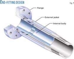
The end fitting must maintain the integrity of the pipe structure, seal to the inner and outer extruded layers, and provide a fixture to transmit tension and pressure loads to the pipe structure. Flexible steel pipe terminates with a simple API 17K-type swaged-end fitting, rather than the larger and more costly API 17J-type end fittings. Years of use on rubber and thermoplastic hoses have proven the utility of swaged-end fittings.
Fig. 7 presents a cutaway of the basic end-fitting design.
A specialized hydraulic press attaches the end fitting to the pipe.
The end-fitting ID after installation is typically 3 mm smaller than the ID of the pipe. The end fittings are normally electrically continuous with the pipe. Table 1 shows pipe electrical resistance. End fittings can be optionally fitted without electrically connecting them.
The end fitting terminates at an end connector designed to attach to steel pipe, generally an ANSI raised-face flange. A pipe stub end for butt-welding to pipes can also act as the terminus.
The ANSI flange joint end connector consists of a stainless hub end factory welded to the end fitting, and a carbon steel lapped flange. The lapped flange acts as a swivel until the flanges are bolted together.
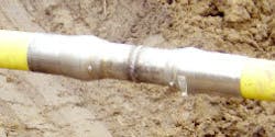
Installing a standard ANSI raised-face gasket, normally a spiral wound 316 stainless steel gasket, and bolting the flanges together with standard studs and nuts accomplishes flange up. Most installations do not use steel brackets to hold the flanges in a fixed location. Fig. 8 shows a butt-welded midline connection.
Reels
Road-portable steel reels supply flexible steel pipe. The reels generally measure 3.7 m (12 ft) in diameter and 2.6 m (8.5 ft) wide. Roughly 2 km of 2-in. pipe, 1 km of 3 or 4-in. pipe, or about 0.5 km of 6-in. pipe fit on a reel.
Onshore qualification
Onshore flexible steel pipe design uses API 17J-approved methodologies and materials, and the pipe capabilities are well within previously qualified limits of pressure, tension, and collapse. They can therefore be considered fully qualified to API applicable standards, even without additional qualification testing conducted specifically on flexible steel pipes.
Tests conducted in accordance with API RP 17B on flexible steel pipes and end fittings have characterized and further qualified the product. Both the API 17J controlling the pipe design and the API 17K controlling the end-fitting design require testing and qualification according to API RP 17B. Design methodology and safety factors are the same for both specifications.
The API documents consider the end fittings qualified from the burst and axial tension tests conducted on the pipe samples. For conservatism, the ISO Technical Specification for RTP qualification governed elevated temperature (end-fitting integrity) tests.6✦
References
1. API 17J, “Specification for Unbonded Flexible Pipe,” 2nd Edition, 2001.
2. API 17K, “Specification for Bonded Flexible Pipe,” 1st Edition, 2001.
3. API RP 17B, “Recommended Practice for Flexible Pipe,” 3rd Edition, 2002.
4. ISO 13628-2, “Petroleum and Natural Gas Industries-Design and Operation of Subsea Production Systems-Part 2: Flexible Pipe Systems for Subsea and Marine Riser Applications,” 1st Edition, 2000.
5. ISO 10420, “Petroleum and Natural Gas Industries-Flexible Pipe Systems for Subsea and Marine Riser Applications,” 1994.
6. ISO Technical Specification 18226, “Reinforced Thermoplastic Piping Systems for Gaseous Fuels,” 2003.
Based on presentation to NACE 2006 Northern Area Western Conference, Calgary, Feb. 9, 2006.
Butt welding often completes the field connection of flexible steel pipe (Fig. 8).
The authors
Dana Fraser (dana.fraser@ wellstream.com) is a senior technical advisor at Wellstream International in Panama City, Fla. He has worked for Wellstream for more than 15 years. He previously served in engineering and quality assurance capacities for Vermont Semiconductor and Fairchild Semiconductor in Vermont and Maine, respectively. He holds a BS in mechanical engineering from the Massachusetts Institute of Technology, and is a registered professional engineer.
Andy Ethridge ([email protected]) is onshore technology development lead at Wellstream International in Houston. He has been an employee of Wellstream for more than 10 years. Prior to joining Wellstream, he was employed as a senior materials engineer by United Defense and Aerojet. He holds a BS in materials engineering from the University of Alabama at Birmingham. He is a 10-year member and past section chairman of NACE International and a 20-year member and past section chairman of ASM International.
