P. 2 ~ Continued - Research nears deepwater intercontinental gas pipeline
Displaying 2/4
View Article as Single page
Optimizing WT
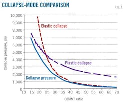
Two simple mechanical relationships, elastic collapse and plastic collapse, describe current generally held failure modes.
Elastic collapse defines a region where OD is large compared to WT. The resultant flexible geometry allows the cylinder to deform and fail while the material is behaving elastically (Equation 1).
The material's elastic modulus (E) and thickness-diameter ratio (t/D) govern pipe failure in this instance.
A pipe thick in relation to its diameter, however, doesn't flex enough to become elastically unstable. Instead, the mounting pressures cause the material to deform plastically. The material hardens as it deforms, eventually losing its ability to resist collapse and failing. This is referred to as plastic collapse (Equation 2).
Both of these treatments are simple to derive, but neither accurately describes what occurs at the point of failure. Pipe failure involves a subtle but complex blend of these failure modes (Fig. 3), with factors like shape also playing a part.
Equation 3, from DNV-OS-F101,1 seeks to blend these formulas to provide a continuous transition from one mode to the other using shape as a transitioning parameter.
US design guideline API 1111 and classical treatments by Timoshenko1 and others contain similar expressions.
Each formula, however, yields a different value of t/D, leaving open the question of which is correct and which best describes the mechanics as the cylinder becomes unstable and fails catastrophically.
Analytical mechanics
Development of finite-element packages removed the need for long, complex formulas and delivered increasingly accurate treatments of particular design problems, allowing perfect design of individual components.
Finite-elements packages cannot, however, readily evaluate parameter variations intended to optimize system design. Each change has to be reevaluated through the software and its effect quantified.
Newton's Second Law of Motion (F = ma) shows that a vehicle increasing in mass requires more force to generate the same acceleration. A formula for the prediction of collapse similarly describing what happens to the pipe at the point of failure would allow examination of how material property and shape variations in the pipe and shape could be adjusted to maximize performance. Such a formula would increase pipeline operators' confidence, ensuring material and project integrity should the representation be proven.
Researchers completed the bulk of work addressing deepwater pipeline collapse in the early 1990s during the first evaluation of an Oman-to-India pipeline (OGJ, July 5, 1993, p. 22). Pipes manufactured by the UOE process (U-ing, O-ing, and Expanding), generally the most economical option for subsea applications, received particular attention regarding their collapse capacity (Fig. 4).
The Oman-to-India team subjected more than 20 pipes manufactured in Europe and Japan to rigorous testing, including construction of a hyperbaric chamber capable of simulating service at 3,500-m water depth. Researchers placed all pipes from the various manufacturers in the chamber, pre-bent them to simulate installation strain and recorded the pressure at which instability and collapse occurred, collating and comparing the results. The pipes' collapse pressure averaged 15% lower than expected with the DNV formulation,3 a discrepancy attributed to reduction in compressive strength due to cold forming of the material, the Bauschinger effect.
Displaying 2/4
View Article as Single page


