Research nears deepwater intercontinental gas pipeline
Richard Freeman
Tata Steel
Corby, UK
Research into the collapse and buckling of deepsea pipelines and the UOE method of line pipe production are moving the industry closer to being able to build and operate intercontinental natural gas lines.
Currently, intercontinental transport of natural gas typically occurs via LNG tanker, not pipeline. The movement of natural gas by ship, however, requires a variety of steps—liquefaction, loading, transit, regasification—not required of pipeline transit. A proposed pipeline linking India to the Middle East across the Arabian Sea, for example, would eliminate the need for these steps while at the same time satisfying some of India's growing appetite for natural gas.
Current alternative onshore pipelines, originating in either Turkmenistan or Iran, would transit either or both Afghanistan and Pakistan en route to India, with attendant political and security concerns. A subsea intercontinental pipeline, however, would present many technical challenges.
Deepwater pipelines
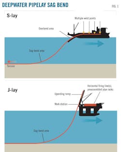
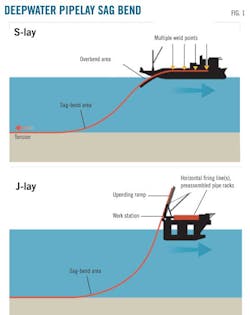
As subsea pipelines are taken to greater depths (generally down to 1,000 m), external pressure may eventually become great enough to buckle and collapse the pipe. The pipe is particularly vulnerable during installation when the pipeline has no balancing internal pressure and the bending during lay (Fig. 1) further stresses its axial fibers.
Despite the apparent simplicity of this failure case, pipe collapse is a complex phenomenon involving plastic and elastic instability. The exact pressure at which the pipe fails is a function of the material properties of the steel, the geometry of the pipe, and its overall surface topography. Local variations in strength and shape lead to an inherent unpredictability of the exact pressure that would lead to catastrophic failure, adding further uncertainty and complication.
Engineers can use theoretical principles to estimate collapse pressure within a specific pipeline and much work has been done to evaluate these principles through full-scale testing. Exploration, however, now demands pipeline performance at such depths and with pipe of such large diameters (an inherent weakness against hydrostatic pressure) that current, conservative expressions and testing regimens form potential barriers to advancement of pipeline technology.
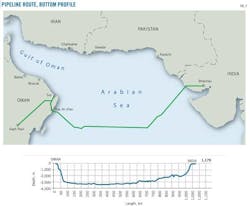
An offshore pipeline bringing natural gas into India from the Middle East would need to have sufficient diameter (26-28 in. OD) to transport gas economically. The pipe's route, however, would reach water depths of nearly 3,500 m (Fig. 2), requiring WT of more than 40 mm for those diameters.
This WT-OD combination is at the edge of current economical pipe-forming capabilities and would require construction of a specialized fleet of new lay vessels. Any WT reduction would yield significant material, installation, and logistic cost savings when considered along the total 1,100-km route.
Reducing WT by 2.5 mm, for example, would yield savings in material alone of about $80-100 million. A WT reduction could also be the difference between lay-barge capability and not being able to lay the pipe at all.
Optimizing WT
Two simple mechanical relationships, elastic collapse and plastic collapse, describe current generally held failure modes.
Elastic collapse defines a region where OD is large compared to WT. The resultant flexible geometry allows the cylinder to deform and fail while the material is behaving elastically (Equation 1).
The material's elastic modulus (E) and thickness-diameter ratio (t/D) govern pipe failure in this instance.
A pipe thick in relation to its diameter, however, doesn't flex enough to become elastically unstable. Instead, the mounting pressures cause the material to deform plastically. The material hardens as it deforms, eventually losing its ability to resist collapse and failing. This is referred to as plastic collapse (Equation 2).
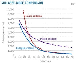
Both of these treatments are simple to derive, but neither accurately describes what occurs at the point of failure. Pipe failure involves a subtle but complex blend of these failure modes (Fig. 3), with factors like shape also playing a part.
Equation 3, from DNV-OS-F101,1 seeks to blend these formulas to provide a continuous transition from one mode to the other using shape as a transitioning parameter.
US design guideline API 1111 and classical treatments by Timoshenko1 and others contain similar expressions.
Each formula, however, yields a different value of t/D, leaving open the question of which is correct and which best describes the mechanics as the cylinder becomes unstable and fails catastrophically.
Analytical mechanics
Development of finite-element packages removed the need for long, complex formulas and delivered increasingly accurate treatments of particular design problems, allowing perfect design of individual components.
Finite-elements packages cannot, however, readily evaluate parameter variations intended to optimize system design. Each change has to be reevaluated through the software and its effect quantified.
Newton's Second Law of Motion (F = ma) shows that a vehicle increasing in mass requires more force to generate the same acceleration. A formula for the prediction of collapse similarly describing what happens to the pipe at the point of failure would allow examination of how material property and shape variations in the pipe and shape could be adjusted to maximize performance. Such a formula would increase pipeline operators' confidence, ensuring material and project integrity should the representation be proven.
Researchers completed the bulk of work addressing deepwater pipeline collapse in the early 1990s during the first evaluation of an Oman-to-India pipeline (OGJ, July 5, 1993, p. 22). Pipes manufactured by the UOE process (U-ing, O-ing, and Expanding), generally the most economical option for subsea applications, received particular attention regarding their collapse capacity (Fig. 4).
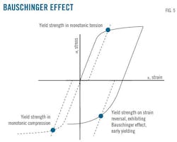
The Oman-to-India team subjected more than 20 pipes manufactured in Europe and Japan to rigorous testing, including construction of a hyperbaric chamber capable of simulating service at 3,500-m water depth. Researchers placed all pipes from the various manufacturers in the chamber, pre-bent them to simulate installation strain and recorded the pressure at which instability and collapse occurred, collating and comparing the results. The pipes' collapse pressure averaged 15% lower than expected with the DNV formulation,3 a discrepancy attributed to reduction in compressive strength due to cold forming of the material, the Bauschinger effect.
The Bauschinger effect is not fully understood but adheres to this general principle: When a material experiences a tensile stress, it first generates an elastic strain and eventually begins to yield, at which point the relationship between the stress and the induced strain becomes non-linear and the material begins to transform plastically (Fig. 5). During plastic transformation the resistance of the material to strain reversal also lessens. Removing tensile stress and then applying the opposite, compression, causes compressive yield to occur earlier.
This series of events occurs during cold-forming of UOE pipe. The final step in UOE manufacture is pipe expansion, the E in UOE, exposing the pipe to tensile stress and reducing its performance under compression.
The first compressive stress the pipe encounters after manufacture is hydrostatic compression at seabed, justifying the derating of UOE-manufactured pipes' collapse pressure since included in both DNV and API design codes.
Pipes with above-average collapse pressures during the Oman-to-India trial underwent additional research to determine if the higher collapse values stemmed from the manufacturing process.4
Subsequent investigation determined the forming equipment used in manufacturing these pipes allowed lower amounts of expansion and higher levels of compression in the O press stage, seemingly reducing Bauschinger's effect and improving shape. The overall increase in collapse pressure allowed removal of the overall 15% derating from the DNV equation.5
Equation 4 simplifies resolution of the resulting DNV cubic equation regarding WT.
Applying Equation 4 to the Middle East-to-India pipeline (3,500-m water depth; 28-in OD, and 42.7-mm WT) yields a WT savings of around 2.5 mm. A thinner pipe wall is both logistically easier and less expensive for a project of this scale.
Additional research is under way at the University of Naples Federico II to find a robust analytical treatment for hydrostatic collapse capable of improving understanding of the mechanisms and perhaps allowing pipe manufacturing or installation procedures to reach the point at which delivery of these large intercontinental infrastructure projects will be feasible.
The theoretical equation under development describes the transformation of the pipe shape through the elastic and plastic transition by building on Gerrard's work, which looked at collapse using the actual shape of the stress strain curve as defined by the tangent modulus, instead of using Young's modulus with an assumed value for the yield strength. This approach allows the new equation to incorporate the strain hardening of the material through the Ramberg-Osgood relationship.
The technique demonstrates good correlation with experimental results and work is underway to add more complexity to the formula to examine the effects of non-homogeneous materials. Once all of the factors driving collapse are understood researchers will attempt to re-simplify the equation for incorporation into design standards. Insight into how shape can influence the onset of collapse could also lead to potential manufacturing improvements.
References
1. Det Norske Veritas, Offshore Standard DNV-OS-F101, "Submarine Pipeline Systems," October 2010.
2. Timoshenko, S.P., and Gere, J.M., "Theory of Elastic Stability," 3rd Edition, McGraw-Hill, New York, 1961.
3. Aamlid, O., Collberg, L., and Slater, S., "Collapse Capacity of UOE Deepwater Linepipe," OMAE 2011 Ocean, Offshore, and Arctic Engineering, Rotterdam, June 19-24, 2011.
4. Stark, P.R., and McKeehan, D.S., "Hydrostatic Collapse Research in Support of the Oman to India Gas Pipeline," Offshore Technology Conference, Houston, May 1-4, 1995.
5. Slater, S., Aamlid, O., Devine, R., Hernandez, D., and Swanek, D., "Qualification of Enhanced Collapse Capacity UOE Deepwater Linepipe, OMAE 2011 Ocean, Offshore, and Arctic Engineering, Rotterdam, June 19-24, 2011.
The author
Manuscripts welcomeOil & Gas Journal welcomes for publication consideration manuscripts about exploration and development, drilling, production, pipelines, LNG, and processing (refining, petrochemicals, and gas processing). These may be highly technical in nature and appeal or they may be more analytical by way of examining oil and natural gas supply, demand, and markets. OGJ accepts exclusive articles as well as manuscripts adapted from oral and poster presentations. An Author Guide is available at www.ogj.com, click "home" then "Submit an article." Or, contact the Chief Technology Editor ([email protected]; 713/963-6230; or, fax 713/963-6282), Oil & Gas Journal, 1455 West Loop South, Suite 400, Houston TX 77027 USA. |
More Oil & Gas Journal Current Issue Articles
More Oil & Gas Journal Archives Issue Articles
View Oil and Gas Articles on PennEnergy.com
