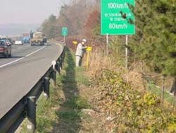
KOGAS stresses pipeline integrity, safety programs
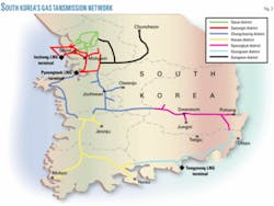
Korea Gas Corp. (KOGAS) operates 1,525 miles of natural gas transmission pipelines in South Korea, a geographically small country but with a high population density. That means pipeline integrity management is very important to the communities it serves.
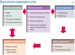
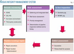
Fig. 1 shows the KOGAS integrity-management system for transmission pipelines. The integrity-management process involves periodic monitoring, risk assessment, in-line inspection, defect assessment, and pipeline repairs.
According to KOGAS’s standards for coating-defect surveys, each buried section of pipeline is assessed by direct current voltage gradient (DCVG) as a commissioning procedure, and every coating defect is repaired before release to the operations department.
KOGAS has a 5-year reassessment interval for operating pipelines. The company uses two main indirect survey methods: DCVG and close interval survey (CIS). This procedure was started in 1999, and all pipelines have now been surveyed.
KOGAS started its in-line inspection (ILI) tool survey in 1997, when the company decided to adopt ILI surveys as a cyclic (indirect) inspection method. Beginning this year, all line segments in operation will be divided into two categories, piggable segments and unpiggable segments. This will allow KOGAS to incorporate direct assessment (DA) procedures into the unpiggable segments, which would include DCVG and CIS as major indirect survey techniques.
This article describes the KOGAS pipeline integrity-management system.
Corrosion control
The principal methods for mitigating corrosion on underground pipelines employ coatings and cathodic protection (CP). KOGAS uses impressed-current cathodic protection on its underground pipelines. Rectifiers are the source of impressed-current power.
KOGAS uses an impressed-current system and a sacrificial-anode system for cathodic protection. In the company’s standard for cathodic-protection design of underground pipelines, impressed-current systems are divided into two types: deep well-anode type and shallow bed-anode type. KOGAS usually applies deep-well anodes to transmission pipelines and shallow-bed anodes to compressor stations. KOGAS has 124 deep-well anode and 77 shallow-bed anode locations.
Following are criteria for cathodic protection of underground or submerged pipelines:
- Negative potential of 850 mv-saturated copper-copper sulfate referenced electrode (CSE).
- Negative potential of 950 mv CSE-used in the case of microbiologically influenced corrosion (MIC). The survey cycle for transmission-pipeline potential is every 3 months.
Most of the coating is polyethylene. According to the KOGAS specifications for polyethylene coating, a three-layer coating is, in principle, applied to all pipes except for bends and fittings. It also is applied to river crossings and offshore pipeline sections.
Another coating system, however, may be employed if specified. In principle, a single-layer coating is applied to bends and fittings. Heat-shrinkable material is sometimes applied to girth welds during construction, while cold tape is used for coating repairs on operating pipelines.
Assessment, management
KOGAS operates its own pipeline integrity assessment and management program (PIAMS) which runs on web browsers. The system works on the KOGAS nationwide intranet.
This unique system was created about 6 years ago when KOGAS began a program to reduce the costs of pipeline management. This program largely consists of three categories: pipeline integrity management, pipeline integrity assessment, and rehabilitation.
Pipeline integrity management consists of the following subcategories:
- Potential survey (P/S, CIS).
- Coating maintenance (DCVG).
- Pipe defect maintenance.
- Interference of stray current and alternative current.
- Rectifier maintenance.
- Underground steel casing pipe.
- River and offshore crossing pipelines.
- Excavation and soil resistivity.
During the third quarter of each year, the plan is reviewed and budgets created for the following year, based on the results of the risk assessments.
The KOGAS intranet on-line database is updated through pipeline field measurements entered at the branch offices. KOGAS currently operates three LNG terminals and eight branch offices. Risk-assessment results determine the appropriate integrity-assessment method.
The rehabilitation plan determines the most effective mitigation measures for the identified threats. Those methods can be in-line inspection, direct assessment, and other methodologies. Pipeline integrity assessment checks all pipeline sections associated with the risk factor.
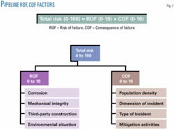
Total Risk is typically described as two primary factors, Risk of Failure and Consequence of Failure. Fig. 2 describes Total Risk.
Risk of Failure (ROF) is the mathematical probability that some adverse event will occur. ROF factors consist of corrosion, third party, mechanical integrity, and environmental situations surrounding the pipeline.
Consequence of Failure (COF) is the result of that event. The factors include population density, dimension of the incident, type of incident, and mitigation activities. ROF consists of 56 detailed assessment items, while COF contains 13 detailed assessment items.
This system can also be utilized as an electronic monitoring system of a pipeline’s cathodic protection. KOGAS entered all available data from 1996 to the first half of 2003. The first risk assessment after development of this system was performed in third-quarter 2003. At present, the total risk number (COF × ROF) in assessment criteria should be less than 15.0, and ROF should be less than 3.505.
These figures will probably change after 2 or 3 years’ trial and error because the criteria are not perfected. The integrity-management program will be continuously customized to meet KOGAS’s unique conditions.
According to the results of risk assessment in 2003, the Gwaneum-Jungni segment exceeded the risk-assessment criteria with a total risk 15.157 in 153 segments. The highest risk factor in this section is polarized potential and stray current. After the polarized potential, the stray current, and ILI surveys were applied last year; this section is now in good condition. Based on the risk assessment being performed, KOGAS selected the appropriate integrity assessment, which is in-line inspection.
In 2004, in-line inspection of the Gwaneum-Jungni section with a high-resolution MFL tool yielded good results. There were no defects to be repaired on the pipeline segment.
A caliper tool was run on July 27, 2004. This section of the pipeline is 6.5 miles (10.616 km) in length, and the OD is 20 in. The nominal WT is 0.47 in. (11.9 mm), with an additional bend thickness of 0.55 in. (14.3 mm). The pipeline was constructed from Grade API 5L X-65 ERW pipe in 1995.
A high-resolution instrumented tool was launched on Aug. 24, 2004. The survey tool traveled through the pipeline using natural gas as propellant. The survey time was 2 hr 5 min, resulting in as average speed of 1.4 m/sec. This pipeline section had not been inspected previously, and there are several anomalies on this section that do not display typical characteristics associated with corrosion. The equation used in this inspection was ASME B31G, safety factor 0.4.
KOGAS performed its second risk assessment on the system with PIAM in 2004. When the first assessment was performed in 2003, the database still had some minor problems and some data errors, which later were corrected by the operator. (The data for risk assessment can be obtained from the operator in charge of a local transmission pipeline’s cathodic protection.)
Operators have corrected some construction data, pipeline information, and possibly modified system errors. This system will be evaluated periodically and modified to reflect improved technologies and new environment. Data also will be updated and corrected to reflect new information when necessary.
In-line inspection
Intelligent pigs for in-line inspection can now provide most of the information required about the condition of a pipeline. This allows the operators regularly to examine a pipeline to ensure it remains in good condition.
Since 1997, KOGAS has inspected 720 miles of its pipelines using in-line inspection technology. This represents 47% of the company’s pipeline system. The inspections began at the 26-in. diameter section between Pyeongtaek and Mokgam.
The entire pipeline can be divided into three categories: piggable segments, unpiggable segments, and segments less than 10 years old. The pipelines under 10 years old represent only 380 miles.
KOGAS does not have the same high-consequence area (HCA) regulations found in North America. If there are sections older than 10 years at any location of the country, they receive in-line inspection regardless of HCA because of the population density.
In the KOGAS sysem, about 155 miles would be too costly to make piggable and 21 miles cannot be pigged at all due to low pressure. The operating pressures of these unpiggable sections are less than 9 kg/sq cm. There currently is no technology for propelling a tool and maintaining its speed without excursion in running through the line by low-pressure-gas product. KOGAS, therefore, has even considered liquid batching, using water instead of its natural gas product as propelling force.
There are two major types of intelligent pigs, the geometry pig and the magnetic flux leakage pig (MFL). The geometry pig measures ovalities, expansion, and reduction of ID, dents, wrinkles, mapping, etc. An MFL pig locates and measures any loss of pipe-wall thickness due to corrosion, gouges, or other causes. KOGAS has developed a geometry pig named KogasCalGeo, and by the end of 2004 had used it to inspect about 300 miles of its pipelines.
A prototype MFL pig also has been developed and tested. The company plans to build a 30-in. OD, 300-m pipeline test facility at the Incheon LNG terminal. After testing, this pig will also be used in the KOGAS pipeline system. The total budget is $5 million and development should take about 7 years.
Pipeline classification change
Korea’s pipeline areas have been defined as Class A and Class B, according to KOGAS’s choices for gas pipe thickness.
Class A is city planning areas (residential, commercial, industrial, and green belt), suburbs to be city-planned, areas adjacent to cities or towns, areas with heavy traffic, and areas with a density factor of 46 or more. In Class A, the design factor is 0.4.
Class B includes all areas other than Class A and areas with density factors less than 46. In the case of Class B, a design factor of 0.5 is applied.
The density factor is the number of households for each 1-mile strip centered on the pipeline with a width of 650 ft on each side. (In the case of the number of households in a building complex, such as an apartment building, the households in the building are counted as independent households.)
The distance between block valves is closer than before. It also means three classifications associated with distance between valves were changed to two classifications, which is 5 miles for Class A and 10 miles for Class B. The 15-mile requirement for Class C was dropped in 1997.
External corrosion DA
KOGAS uses only DCVG and CIS for indirect inspection. The direct assessment (DA) process has not been used regularly. KOGAS’s pipeline system carries gas from LNG, and the risks from internal corrosion and stress corrosion cracking are negligible.
The major concerns for the transmission pipeline involve external corrosion, and most of the corrosion has been found beneath the disbonded coating of girth weld joints and related to microbiologically influenced corrosion. The most important parameter is the corrosiveness of the soil in this type of corrosion.
KOGAS plans to establish DA for its unpiggable sections. The proposed DA procedure emphasizes soil-resistivity surveys and follows the guidelines of relevant codes such as NACE PR0502.
Damaged pipeline coatings are repaired according to results of DCVG; however, KOGAS will soon start integrity assessment with ECDA according to RP NACE 0502-2002. The first section will be the 12.5-mile Jochiwon-CheongJu segment. After this project, KOGAS will decide if ECDA will be adopted as part of its integrity-management program.
GIS pipelines
Gas explosion accidents in Seoul in 1994 and Taegu in 1995, respectively, accelerated the development of an integrated underground facilities management system. The South Korean government is developing the system in the areas of sewerage, water, communication, gas pipelines, electricity lines, heating, and oil pipelines.
KOGAS’s geographic information system (GIS) includes as-built drawings, pipeline construction records, reports of radiographic examinations, information on third-party activities, and rights-of-way, which may be accessed by operators using the intranet system. KOGAS has accumulated this database of buried pipelines and pipelines under construction since 1996.
KOGAS has surveyed its pipeline routes using ground-penetrating radar (GPR). After marking the pipeline’s route and depth acquired by GPR, these marked points are allocated global positioning system (GPS) coordinates, which are entered into South Korea’s National Geographic Information System (NGIS). KOGAS has almost completed its database of as-built drawings on the pipeline system and now has surveyed by GPS more than 700 miles of the total system.
The goal of the NGIS master plan is to develop environmentally healthy land as well as to promote national competitiveness and productivity. The success of the NGIS master plan should mark a turning point in the country’s management system.
Realtime monitoring by GPS
KOGAS maintains a realtime-based location information system by GPS for its patrol vehicles as part of improving pipeline safety management. This system provides quick response and appropriate measures for emergencies that may occur with a gas transmission pipeline.
Each patrol car is equipped with a GPS module that enables it to display the pipeline mapping system from GPS coordinates.
The following are the main functions on the web-based system:
- Display the digital pipeline network (zoom in, zoom out).
- Display the realtime-based location of area patrol vehicles on the screen in the central control center.
- Update display data of each individual vehicle every 3 min.
- Display each vehicle’s route.
- Transfer stored back up data.
Block valves with MOV
KOGAS installs block valves in transmission pipelines according to South Korea’s City Gas Business Law. As mentioned, the distance between block valves is set for both Class A and Class B areas. If an incident occurs, each motor-operated valve (MOV) could be closed by a control center operator to isolate a pipeline section at the incident spot.
To avoid explosions and fire, an operator can ventilate gases from the pipeline section. The MOV is always monitored by a control center.
Close monitoring
Test units above the pipelines measure the cathodic protection installed within 300 m for sacrificial anodes and drainage systems and within 500 m for impressed-current systems. Gas-leak probes check for gas leaks from underground piping at both ends of steel casings for road crossings and stopple fittings where the line is hot-tapped.
Signs mark the location of buried pipelines at unpaved roads, on the side slopes of paved roads, and in roadside trenchs. The distance between signs is 100 m or less, and they are also located at every turn and intersection. Signs are placed every 25 m if a housing area is near a gas pipeline.
A marker identifies pipelines passing under paved roads, paved sidewalks, and intersections. Installation spacing is 50 m or less for paved roads and sidewalks.
KOGAS’s pipeline patrol checks each section of pipeline twice a day by vehicle. There are areas, however, that patrol vehicles cannot approach to check for damage or third-party activities, so that the company also uses foot patrols to monitor pipelines routes.
Patrol teams consist of two persons. One patrols on foot along the surface of the pipeline, while the other drives the car along the pipeline route. The pedestrian patrol inspects 1-2 km/day and completes its section of a pipeline once every 3 months. The vehicle patrol makes two round trips every day, even on holidays.
KOGAS also operates a local-area monitor system. In some areas, a person who lives near a pipeline performs the regular inspection on a pipeline instead of a patrol car, when a patrol car cannot approach the area because of the terrain. The local-area monitor calls the KOGAS area control center twice each day to report the inspections.
Third-party monitoring
KOGAS has a research and development program to develop on-line monitoring for pipeline damage by third-party construction. The main focus of the project is the detection of vibrations from construction equipment that produce a distinguishing vibration pattern.
A prototype has been built and installed at a test section. The device would cover about a 10-km range. The device has an accelerometer and signal-acquisition unit, and the measured signal is transmitted to the server via the internet. When the signal from third-party construction is detected, the server automatically gives an alarm and sends a message to the patrol team.
Based on a presentation at Gastech 2005, Mar. 14-17, 2005, Bilbao, Spain.
The authors
SungBaek Hong ([email protected]) is head of Korea Gas Corp.’s technology planning team at the company’s headquarters in Sungnam City. He joined KOGAS in 1985 and worked in pipeline construction and operations until he joined the pipeline maintenance department in 1996. He has worked with cathodic protection and ILI operations since 2003. Hong holds a BS in electrical engineering from Soong-Sil university.
YoungGeun Kim is a project manager in Korea Gas Corp.’s research and development center, Sungnam City. Since joining KOGAS R&D in 1996, he has been involved with the corrosion protection team in developing a corrosion-monitoring program for buried pipelines. Kim holds a PhD in metallurgical engineering from Seoul National University.
DongGeun Han ([email protected]) is a manager in the pipeline improvement section at Korea Gas Corp. headquarters in Sungnam City. After joining KOGAS in 1993, he worked for 7 years at the Pyeongtaek LNG terminal construction office. He later transferred to the transmission pipeline offices and has become active in pipeline improvement activities. Han holds a degree in metallurgical engineering from JeonBuk University.
