Method calculates sand velocity, hold-up in flowlines
Paul Stevenson
Centre for Multiphase Processes
Callaghan, Australia
Rex B. Thorpe
University of Surrey
GuilDford, UK
A relatively simple method of estimating sand velocity and hold-up in multiphase flowlines allows a design engineer to determine whether a producing well needs a sand-exclusion system at a subsea wellhead.
Estimating the behavior of sand in multiphase flowlines is difficult and complicated. An estimation of solids rate and in situ hold-up, however, is necessary to determine whether a production operation requires costly sand-exclusion systems.
The method presented in this article provides the tools for the engineer to make such an evaluation.
Once such estimates have been made, however, the engineer should proceed with the utmost caution. For instance, the method discussed here assumes that water-cut is zero. If the water-cut is small but not zero, the sand will become water-wet and may form cohesive clumps that are much more difficult to transport than isolated particles.
Another assumption is that the flowline is absolutely horizontal. In long flowlines this is unlikely, and one may expect terrain-induced slugging. For such flows, one may need to adjust the long-slug model discussed here.
Sand settling
Settled sand in a subsea oil or gas flowline can adversely Affect production rate and also creates an environment conducive to electro-chemical corrosion. Such deposits must either be avoided by sand management or sand exclusion.
This article will furnish the design engineer with the tools to predict whether sand present in a flowline is likely to be transported to the topsides where it may be removed from the production fluids. Otherwise, it may be necessary to fit or retro-fit sand-exclusion systems, such as gravel traps at the subsea wellhead.
In general, operators prefer sand management, such as removal at the topsides, more than sand exclusion at the subsea wellhead because of lower capital cost, less maintenance, and higher reliability.
This article presents methods of predicting the velocity of sand in horizontal flowlines carrying intermittent (slug and plug) flow and stratified flow. This information can be used to estimate volumetric hold-up of solids within the flowline that in turn will determine whether it is likely that the sand will be transported to the topsides.
Pilot-plant scale multiphase flow-loop studies at the Department of Chemical Engineering, University of Cambridge, have verified many of the presented methods. An exception to this is the long-slug model that is likely valid for industrially scaled flowlines.
Sand velocity
Determination of the structure of intermittent flow within a pipeline is most difficult. Recently, Hale showed that the exact nature of the flow depends on inlet conditions,1 a fact that most established models and computer codes for intermittent flow do not recognize.
The behavior of solids in such a flow regime is clearly more problematic. To estimate the behavior of sand in intermittent flow, this article adopts the rather simple long-slug model for intermittent flow.
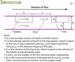
The long-slug model is based upon the approximation that in the film phase, the liquid film thickness, underneath the gas bubble, falls to its equilibrium height immediately upstream of the end of the slug body. Fig. 1 shows a schematic representation of this simplified flow.
The use of the long-slug model is justified because:
- Slugs in real flowlines are long and the distance for film height to equilibrate is small compared to the film length. For example, Scott observed slugs as long as 300 m in the Prudhoe Bay pipeline.2
- Experiments by Stevenson3 and the energy balance performed by Stevenson4 show that the slug nose does not materially enhance solids movement.
- Highly sophisticated mechanistic models and computer codes are unlikely to predict the nature of slug flow better than the long-slug model.
One may approximate sand transport in intermittent flow by a hybrid of hydraulic conveying and stratified flow, which are both steady flows. In the slug section, the flow at the slug nose is highly nonuniform, but this nonuniformity will be diminished with distance; and in a long slug, the uniform section will dominate the particle velocity. The film section similarly tends to stratified flow.
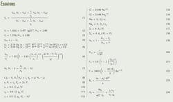
It is therefore appropriate to estimate the velocity of the particle in the two distinct sections. Thus the average velocity of sand in the long-slug model of intermittent flow may be written as Equation 1 (see equation box).
In Equation 1, VPS is the particle velocity in the slug section and VPf is the particle velocity in the film phase.
The following sections discuss methods for calculating the terms required by Equation 1.
Slug-nose velocity
Equations 2 and 3 provide the slug-nose velocity (Vt) from a correlation for the translational slug-nose velocity suggested by Manolis.5
In the equations, the D is the pipe diameter and the mixture Froude number is calculated as Frm=j(gD)-0.5.
Slug-section particle velocity
Stevenson noted that in hydraulic conveying at low solids concentration, one can estimate the average particle velocity (VPS) by calculating the difference in mean liquid velocity and the critical liquid velocity required for incipient motion of a particle.3 By approximating the transport of particles within the slug section as motion in simple hydraulic conveying, one can obtain the average particle velocity in the slug section with Equation 4.
One may calculate the critical liquid velocity for first particle movement, VC, by the method of Stevenson, who developed a theory for the incipient motion of hemispheres from the viscous sublayer at a pipe wall.6
This method selected a hemisphere as a better representation of a sand grain than a sphere because hemispheres, in common with sand, tend to commence motion through dragging. Spheres, on the other hand, commence motion by rolling.
One can calculate the critical velocity with Equation 5. In it:
- f is the coefficient of static friction between particle and wall. One may use an f = 0.55 as an estimate in the absence of an experimental value.
- s is the ratio of particle to liquid densities. Silica sand has a density of about 2,650 kg/cu m.
- R is the radius of the hemisphere or for practical purposes one-half of the sieving diameter, d, of the sand.
- n is the liquid kinematic viscosity.
- Q is the shear rate in the viscous sublayer, which may be calculated using a standard Blasius formulation.
Equation 5 depends on particle size. The design engineer often will not have particle size data unless someone has analyzed the sand samples collected in the slug catcher on the topsides.
It is thus worth mentioning that the authors have sand size data from two anonymous fields. One reports sand grains in the range 105-210
Film-section particle velocity
The method calculates the sand behavior in the film section as if the particle were being conveyed by stratified flow. Stevenson developed Equation 6 for average particle velocity (VPf) in smooth stratified flow.7
In the equation, Df is the hydraulic diameter of the liquid film, which is 4Af/Pf. The Pf is the wetted perimeter due to the film.
Note that Equation 6 has a similar form to Equation 4 because particle velocity is approximately equal to the liquid velocity in the film minus some type of critical velocity.
Flow structure
In the long-slug model, it is assumed that each successive slug unit is the same. The model for slug flow requires three closure parameters; the liquid hold-up within the slug body, HS, the translational velocity of the slug nose, Vt (already given in Equations 2 and 3), and the ratio of the slug length, Ls, to the film length, lf.
In this simple model, the cross-sectional area of the film is constant along its length, so that Vf is a constant along the film section.
The computation of the three unknowns, lf/Ls, Af, and Vf, requires three independent equations, as follows:
- A Lagrangian balance on the flows of the liquid phase around the slug nose (Equation 7).
- A liquid balance around both inlet and outlet of the system (Equation 8).
- Equating of the axial pressure gradients in the film and bubble, expressed as Equation 9.
One may conveniently calculate the shear stresses in Equation 9 from the appropriate friction factors (Equation 10-12).
For turbulent flow, one should use the standard Blasius formulation for the liquid and gas friction factors found with Equations 13-14. In these equations, Df and Dg are the liquid and gas phase hydraulic diameters (Equation 15-16) in which:
- Af and Ag are the cross-sectional areas of the liquid and gas strata, respectively.
- Pf and Pg are the wetted perimeters of the liquid and gas strata, respectively.
- Pi is the chordal width of the interface between gas and liquid strata.
Cfi is approximately equal to the gas phase friction factor for smooth stratified flow. But for stratified wavy flow, the friction factor is higher, resulting in a faster moving film phase and easier sand transport.
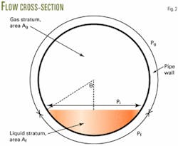
The flow may be most conveniently solved by expressing the strata areas and perimeters as a function of the half angle subtended by the interface at the pipe center, shown as θ in Fig 2.
Then, Af = 0.25πD2(θ - sinθ cosθ), Ag=0.25πD2(1 - θ + sinθ cosθ), Pf=θD, and Pg=(π-θ)D, Pi=sinθD. Equations 7, 8, and 9 may then be solved simultaneously, iterating around θ.
The calculation also requires the liquid hold-up within the slug, HS, such as Andreussi semi-empirical correlation for HS (Equations 19-23).8
In Equation 21, D0 = 0.025 m, and in Equation 22, the θ is the pipe inclination and the Bond number is determined by Equation 23.
The Andreussi correlation is applicable for D>0.04 m.
After determining the structure of the flow and calculating the particle velocities in the film and slug phases, one can obtain the average particle velocity, VP, from Equation 1.
In situ sand hold-up
One can use Equations 4 and 6 to calculate the velocity of isolated particles in the slug and film, respectively. These equations are not relevant for cases with significant in situ solid hold-up.
The authors suggest that the isolated particle approach discussed in this article is only valid if the calculated in situ solids hold-up is less than about 100 ppm. Otherwise, if solids fractions much greater than this are expected, one should evaluate the method of Gillies,9 which extended existing theories for the hydraulic conveying of high solids hold-up slurries to intermittent flow.
Sand loadings in typical North Sea flowlines are believed to be 5-40 lb/1,000 bbl produced. This corresponds to 0.014-0.11 kg/cu m sand in produced crude or a delivered volume fraction in the range of 5-40 ppm.10
One may calculate the in situ solids fraction with Equation 24, which was derived by Stevenson.10
In Equation 24:
- Ls is sand mass in sand per cubic meter of oil produced.
- jf is superficial oil velocity.
- VP is average particle velocity.
- ρS is sand density.
It is, however, acknowledged that delivered solids fraction is not always less than 100 ppm. It is possible that sand collects at dips in flowline so that the local solids volume fraction could be much larger than 50 ppm.
Also, the authors are aware that primary-produced heavy oil fields, such as the Canadian tar sands, the Venezuelan Orinoco Belt, and the steam flooded fields After steam breakthrough can produce larger amounts of sand.
Flowlines carrying very heavy oil have been reported with sand loadings of about 11,000 lb sand/1,000 bbl produced crude. Clearly, at such high sand loadings, substantial inter-particle interaction will occur. F
References
- Hale, C.P., Hewitt, G.F., King, M.J.S., Lawrence, C.J., Manfield, P.D., Mendes-Tatsis, M.A., and Odozi, U.A., "Slugs, waves and the law of the jungle," 10th International conference on Multiphase Flow, Cannes, France, June 13-15, 2001.
- Scott, S.L., Shoham, O., and Brill, J.P., "Modelling slug growth in large diameter pipes," 3rd International Conference on Multiphase Flow, The Hague, Netherlands, May 18-20, 1987
- Stevenson, P., Thorpe, R.B., Kennedy, J.E., and McDermott C., "The similarity of sand transport by slug flow and hydraulic conveying," 10th International Conference on Multiphase Flow, Cannes, France, June 13-15, 2001.
- Stevenson, P., and Thorpe, R.B., "Energy Dissipation at the Slug Nose and the Modelling of Solids Transport in Intermittent Flow"; accepted for publication, Canadian Journal of Chemical Engineering, 2002.
- Manolis, I.G., High pressure gas-liquid slug flow, PhD thesis, University of London, 1995.
- Stevenson, P., Thorpe, R.B., and Davidson, J.F., "Incipient motion of a small particle in the viscous boundary-layer at a pipe wall"; in press, Chemical Engineering Science, 2002.
- Stevenson, P., and Thorpe, R.B., "The Velocity of Isolated Particles Along a Pipe in Smooth Stratified Gas-Liquid Flow," AIChE Journal, Vol. 48, 2002, pp. 963-69.
- Andreussi, P., and Bendiksen, K., "An investigation of void fraction in liquid slugs for horizontal and inclined gas-liquid pipe flow," International Journal of Multiphase Flow, Vol. 15, pp. 937-46
- Gillies, R.G., McKibben, M.J., and Shook, C.A., "Pipeline flow of gas, liquid and sand mixtures at low velocities," Journal of Canadian Petroleum Technology, Vol. 36, 1997, pp. 36-42.
- Stevenson, P., and Thorpe, R.B., "Towards understanding sand transport in subsea flowlines," 9th International Conference on Multiphase Flow, Cannes, France, 1999.
The authors
Paul Stevenson is a research associate at the Centre for Multiphase Processes, Australia. He previously was at the Department of Chemical Engineering, University of Cambridge, where he investigated sand behavior in flowlines. Some of this work was funded by the second stage of the EPSRC transient multiphase flow's co-ordinated research project. Stevenson holds an MA, MEng, and PhD from the University of Cambridge.
Rex Thorpe is professor of multiphase engineering at the University of Surrey, UK. He has held visiting fellowships at Princeton University and the Centre for Multiphase Processes, Australia. Thorpe holds an MA, MEng, and PhD from the University of Cambridge and is a member of the Institution of Chemical Engineers.


