Technique, nozzle enhance coiled tubing wiper-trip efficiency
Operators in the US Gulf Coast region complete most wells with some kind of sand-control measure, ranging from resin-coated sand to pre-packed gravel pack screens. Resins break down, however, screens become flow cut, and gravel-packs fail; wellbores require cleanouts.
A new nozzle and cleanout technique for coiled tubing make the wellbore cleanout process more efficient, enabling smaller size coiled tubing to clean wellbores effectively with ordinary fluids and with fewer barrels pumped during the cleanout operation.
Pressure-depleted reservoirs tend to produce unwanted formation water. Water influx often brings sand and silt into the wellbore.
Well fluids at low velocities will not transport debris out of the well but will allow solid particles to settle in the rat hole or, in the case of higher hole angles, to the low side of the wellbore. Sand building up into a bed on the low side of the hole can eventually cover perforations and plug the tubing.
Invariably, operators get sand and proppant in the wellbore. Sand-maintenance shutdowns and remedial work have become an expensive problem.
Wiper-trip cleanout
Operators have used coiled tubing for more than 30 years in the US Gulf Coast region for wellbore cleanouts, circulating wellbore fluids and solids to surface. Coiled tubing is the tool of choice because the operation allows continuous circulation while traveling down the hole.
Coiled-tubing operations have employed a wide variety of fluids to carry sand and solids to surface. Water, gels, foam, and nitrified fluids are among the popular choices in the effort to improve the well-cleaning process efficiency.
An industry "rule of thumb" for vertical wells has held that the wellbore fluid velocity should be at least twice the sand-settling rate in the fluid used. Such rules, however, don't take into account disruptions to the flow profile caused by the coiled tubing's eccentric position in the wellbore and the resulting loss of effective solids transport.
Most wells are not truly vertical, and the coiled tubing's tendency to rest on the side of the casing affects the velocity at which fluids can carry the sand vertically.
Once the sand or solids enter the smaller bore production tubing, annular velocity typically increases to a rate much higher than the sand-settling rate, and transport efficiency increases accordingly.
If the coiled tubing cleanout operations and circulating time can continue long enough to transport the sand from the casing up into the production tubing string, then the operation will easily remove all of the sand from the wellbore.
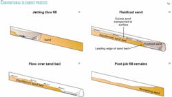
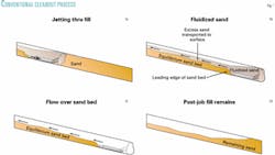
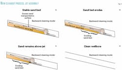
Often, however, the process stirs up the sand and debris in the casing where it stays predominantly in suspension but without being fully transported to the production tubing. The sand resettles to the bottom as the coiled tubing is pulled up the hole (Fig. 1).
The flow geometry in deviated or horizontal wells essentially prevents coiled tubing from lifting medium sized solids in large casing.
The sand has only a short distance to fall to the low side of the casing where it builds into a sand bed. Circulating fluid washes over the top of the bed without entraining or transporting any of the sand further along the wellbore (Fig. 1b).
Ultimately, the sand bed builds to a depth or thickness that reduces cross-sectional flow area, increasing fluid velocity to the point that no further sand deposition occurs.
All subsequent sand from the bottom of the well is now transported, but the sand constituting the bed remains undisturbed (Fig. 1c).
Over the years operators and service companies have used this wiper-trip cleanout procedure to wash sand out of wells, with limited success.
Crews and coiled-tubing units have remained on location for days working up and down the wellbore yet removing only a small percentage of the fill with each attempt, wasting the operator's time and money.
Any experienced wireline operator will attest that he or she has tagged sand high in a well, just after it was cleaned out with coiled tubing (Fig. 1d). Many in the industry lack understanding of the dynamics occurring in the wellbore and are unable to predict the outcome of sand washing operations.
New process, jet assembly
In light of past coiled-tubing job failures and less than optimal jobs, the industry has become aware of the need for effective computer modeling to predict multi-phase flow conditions, pressure losses, and tubing forces within the wellbore and coiled tubing.
Service companies have developed computer software to meet this need. Engineers have collected and compiled data for the past 20 years, creating a coiled-tubing software platform, which BJ Services Co. calls "CIRCA."
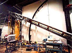
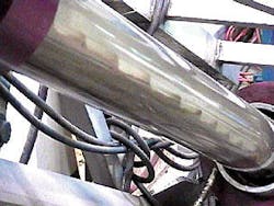
The coiled-tubing job modeling software includes a module for solids removal job design, which the company calls "Tornado Pro". The software is based on data from numerous flow tests conducted with use of a flow simulator in the company's Calgary research lab (Figs. 2 and 3).
The computer software simulator can accurately model the sand-washing process at various hole angles, pumping rates, and fluid types.
Based on understanding fluids and solids transport, engineers and scientists have developed a new method for clearing particulate solids from deviated and horizontal wellbores.
The solids-removal software models the sand-washing process as the coiled tubing moves down into the wellbore. It predicts the amount of sand entrained in the fluid and subsequently deposited as a sand bed on the low side of the hole and predicts the balance, if any, of sand transported up and out of the wellbore (Fig. 4a).
Once the coiled tubing reaches the bottom of the well, the model further predicts the time required to reach an equilibrium condition where an "equi librium sand bed" is formed that simply stays in place and is not altered by further circulation at existing pump rates (Fig. 4a).
Engineers have developed a specialized jetting assembly, which BJ calls the "Tornado tool," that combines switchable forward and rearward facing jetting nozzles as a new element in the wiper-trip cleanout process (Fig. 5).
Once the wiper-trip cleanout process has established an equilibrium sand bed, technicians switch the jetting assembly from the forward to the rearward facing nozzles, creating a rearward facing localized turbulent flow stream. As crews pull the coiled tubing out of the hole the rearward jetting action entrains the front of the sand bed allowing it to be carried out of the hole in the flow stream above the equilibrium bed (Fig. 4a-4c and 5).
Coiled-tubing operations maintain the pull-out-of-hole speed and flow rate that the computer model determined would keep all the sand above the jetting assembly, all the way out of the hole.
Operators have used the process and jetting assembly in nine US Gulf Coast area wells, with the software modeling well conditions and job parameters accurately and the jobs resulting in 100% particulate solids cleanout.
Gravel pack removal
Ocean Energy Inc.'s Eugene Island Block 120 "Pin High" well No. 13 required a through tubing, wash-down of a gravel pack in place. This slanted well, which has 75/8-in. casing to 6,702 ft, has a maximum deviation angle of 26°. The operator completed the well with 27/8-in. tubing to 6,484 ft and vent screen, 6,575-6,702 ft.
The well had produced for 1 month through the gravel pack with vent screen, before sanding up.
The operator had determined that the gravel pack sand had shifted during production, which left an open-flow path for formation sand to enter the wellbore.
The critical element of the planned cleanout procedure required the coiled tubing to wash down across the vent screen assembly to the bottom perforation, to ensure that no formation sand or proppant was left around the screen.
The operator would gravel-pack the perforations again with proppant up to 6,604 ft and lay-in a cement cap to prevent the same failure from occurring again.
To ensure job success, the coiled tubing had to remove 100% of the existing gravel pack sand and formation sand, for the job to succeed. Maintaining proper hydrostatic control was critical to prevent formation sloughing from compromising the completion.
In addition, any formation sand left around the screen assembly would reduce the permeability of the proppant in the new completion. If this were to happen, subsequent work-over operations would be costly because the cement cap above the screen assembly would have to be removed.
Based on the operator's previous experience with the reversible nozzle-jetting assembly, the tool was selected for the job. The job, however, required a nonstandard-slim tool size that the service company had to design and build (Fig. 5).
After computer modeling, engineers selected a nitrified fluid system for the operation.
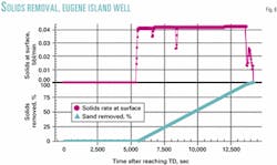
The job with the reversible nozzle-jetting assembly run on 11/4-in. coiled tubing successfully cleaned the gravel-pack sand and formation sand from the wellbore; the computer model accurately predicted all aspects of the cleanout (Fig. 6).
When the new gravel pack was placed, wireline was able to tag the gravel top at exactly the calculated position, indicating that the coiled tubing had cleaned the vent-screen annulus to TD.
The industry has historically performed coiled-tubing cleanouts, not knowing ahead of time all of the job parameters to be expected. Some operators have ordered coiled-tubing jobs and equipment on a call-out basis, resulting in many sand-washing operations that were ineffective due to insufficient planning and job design.
Proppant removal
In another US Gulf Coast area well, an operator performed a through-tubing stimulation and gravel pack (frac-pack) with 20/40 mesh proppant in the well with a maximum deviation angle of 72°. The well was relatively shallow, with 75/8-in. casing to 2,306 ft.
The operator had completed the well with 3½-in. tubing to 1,979 ft and vent screen assembly, 2,030-2,306 ft.
The frac-pack job had screened out above the top of the vent screen, requiring proppant removal before the well could be produced.
In such a large, highly deviated wellbore the high annular velocity required to wash the proppant efficiently generates excessive annular friction, increases risk of lost circulation, and has the potential to get the coiled tubing stuck.
The coiled tubing software (CIRCA) demonstrated that it was not possible to achieve the pump rate required for a conventional cleanout while keeping the pressure inside the 1½-in. coiled tubing reel at a manageable level.
Pumping at 3 bbl/min, with more than 11,000 psi pump-injection pressure, would only remove 85% of the proppant from the wellbore.
The operator's options would have been to use nitrogen to increase annular velocity or use expensive drilling fluids to hold the solids in suspension while washing. While these solutions were viable, the operator would have incurred additional cost and effort as well as increased the amount of equipment needed on a very small location. The use of nitrogen or a drilling fluids system would have required the operator to rent a lift-boat as well.
The operator chose to design a job that uses the reversible nozzle-jetting assembly and was properly modeled with computer software, which proved to be logistically more efficient and less expensive.
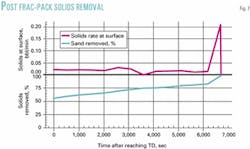
While the well was being washed down, coiled tubing tagged proppant at 1,400 ft, indicating that the job must recover 8 bbl of proppant to clean to the top of the vent screen.
The computer model correctly predicted all aspects of the job, including the time required for proppant to reach surface and pump pressures needed for circulating proppant-laden fluids (Fig. 7).
Crews estimated the total amount of proppant recovered in the surface tanks as 8 bbl, after making the wiper trip and pulling the coiled tubing out of the hole. The well began to flow on its own immediately after the cleanout procedure.
The authors
Doug Hobbs is the coiled tubing account manager for BJ Services in Lafayette, La. He joined BJ through the acquisition of Nowsco in 1996 and has held his current position since then. He has worked in various management, sales, and operations positions in the coiled tubing business along the Gulf Coast since 1978. He has a BS in business administration from Louisiana State University, Baton Rouge.
Charles Liles is a district technical supervisor for BJ Services Co., Coiltech district in St. Martinville, La. He joined BJ through the acquisition of Preeminent Energy Services in 2001. He has worked both offshore and onshore with coiled tubing and nitrogen operations for 6 years and is an SPE member.
