Rerating of compressors, motors debottlenecks hydrocracker

Based on a presentation to the NPRA Annual Meeting, San Antonio, March 26-28, 2000.
A Midwest US refinery added $3.1 million to its bottom line by debottlenecking two hydrogen makeup compressors in its hydrocracker complex (HCC). BP PLC and the refiner worked with the compressor manufacturer to debottleneck both compressors to 112.4 % of their original design flow rates.
The team has recommended further debottlenecking of these compressors to 144.1% of their design capacities in the future. It has also developed a plan to debottleneck the existing motors to 125% of their rated horsepowers with the 144.1% option.
Maintaining and improving compressor reliability and operating flexibility are the guiding principles of the refiner's compressor maintenance program.
Compressor projects
The HCC consists of a hydrocracker, hydrogen plant, naphtha reformer, motor gasoline reformer, and pressure-swing adsorption unit. Although originally designed to process 24,000 b/d of gas oil, its throughput is now 29,000 b/d.
The complex's primary products are hydrogen, gasoline, benzene, toluene, xylene, and a low sulfur distillate-blending component. The volume gain from the HCC is a vital contributor to profitability.
Two makeup compressors compress hydrogen produced by the reformers, pressure-swing adsorption unit, and hydrogen plant, and supply hydrogen to the HCC. These Cooper Bessemer, Model LM-3 compressors boost hydrogen gas from 250 to 1,450 psig at a flow rate of 27.5 MMscfd. The compressors are three-stage units operating in parallel.
Piston sizes on the machines are 19.5 in. for the first stage, 16.25 in. for the second stage, and 11.0 in. for the third stage. The pistons are double acting, pumping gas in the forward and reverse directions. A 3,500-hp synchronous motor drives each compressor.
Projects implemented
Although the unit had plenty of hydrogen gas, it was limited by compression capacity.
In summer 1996, the refiner contracted the compressors' original equip ment manufacturer (OEM), to develop debottlenecking options for the HCC compressors based upon current and future system operations. The refiner carried out a performance test to establish compressor base-line performance.
The refiner gave the OEM two constraints: The options had to be low cost (no major equipment replacement or addition) and allow implementation within a scheduled maintenance window for compressor overhauls. Table 1 lists the initial two options that the OEM presented.
In spring 1997, the project team decided to implement the 6.8% flow increase option on the first compressor during the overhaul scheduled for December 1997.
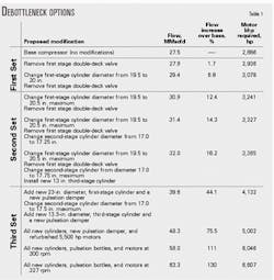
After the project team placed a parts order, the OEM developed a second set of options that allowed more flow (Table 1).
The 12.4% and 14.3% options provided a significant increase in flow for a small incremental cost. The 16.2% option was considerably more expensive because it involved a third-stage cylinder change out.
Motor horsepower was a concern in the second set of options because they cut into API's suggested 10% safety margin. The project team used tests and operating data to show that cutting into this safety margin posed little risk.
An economic evaluation and a review of operational and reliability concerns resulted in a recommendation to implement the 12.4% option for the second compressor during a planned HCC outage in February 1998. Due to long delivery requirements, the project team ordered parts in the first week of December 1997, while implementing the 6.8% option on the first compressor.
The refiner completed debottlenecking the first compressor in December 1997. Two flow performance reviews 3-4 weeks apart validated the expected flow increase of 6.8%. Tests confirmed motor performance and resulted in no reliability concerns.
The 12.4% increased flow conversion in February 1998 also went well. A performance review of the second com pressor confirmed a 12.4% increase in the compressor flow. The first compressor was also converted to 12.4% flow increase at a maintenance overhaul opportunity in January 2000.
Total cost of the two 12.4% revamps was $300,000.
Future projects
Working with the OEM, the team developed a third set of debottlenecking options with yet larger flow increase options with no restrictions on motor horsepower; the only restriction for these options was compressor frame horsepower.
This final set of options involves maximizing piston sizes for each cylinder class and installing larger cylinders (Table 1). The options require significant compressor part replacements and power demand in excess of 3,500 hp.
The synchronous motors were rated for 3,500 hp at 300 rpm and a 0.8 power factor (PF). A study concluded the motors were capable of providing 4,375 hp at 1.0 PF. This change in PF would require no modifications to the existing motors but would require additional capacitors to maintain the refinery power-system balance.
In addition to compressor modifications, the 44.1% option required additional capacity for the first-stage suction intercooler and compressor water-jacket cooler.
The motor manufacturer also calculated torque values for the motors at 4,375 hp. The OEM reviewed these values for the 44.1% option and concluded that the available torque, although reduced, would still meet the compressor requirements.
With the 44.1% flow option, other HCC throughput limits and hydrogen gas production capability limits were reached before encountering makeup compressor limitations. The refinery has set up a team to review the debottlenecking opportunities that may exist in the HCC and hydrogen plant for the next major turnaround.
Compressor rerates
If an initial investigation of the service history, compressor condition, and compressor support systems does not reveal the compressor as a bad choice for a rerate, the engineers next evaluate the effect of new process conditions on the new design. They should consider the frame and rod loading, relief-valve horsepower, damper pressure drop, valve modifications, cylinder sizing, and crankshaft loading.
The compressor OEM, who knows the design evolution of the equipment, can determine if up-rate potential is good. The historical reliability of the LM-3 compressors at this refinery made them good candidates for an up-rate.
Frame, rod loads
The project team checked two important compressor frame design parameters: the frame and rod loads.
Typically, rod load, not input horsepower, induces the highest frame and crankshaft stresses. It is often acceptable, therefore, to exceed the nominal frame rating as long as the rod loading is not exceeded.
Frame horsepower limitations for the LM-3 compressors at the refinery were not a concern because the nominal frame rating was 7,330 bhp and the drive motor rating was 3,500 bhp.
Up-rating a compressor frame is usually possible because past minor design changes often increase the compressor rod-load rating.
Two simple up-rate improvements are upgrading the material and using a rolled (rather than cut) thread manufacturing method. One example is upgrading the clamp bolt used in the eye of the master compressor rod as well as the rod cap.
In some compressor designs, bolting of the crosshead guide to the frame can also be modified to up-rate the rod load. In these instances, the existing frame casting must have the necessary material to support the new bolting.
When calculating rod load, it is important to consider the suction and discharge pressure internal to the cylinder, which produces actual stresses on the equipment.
One way to determine internal pressure is to use the nominal rating under which most machines were furnished, that is, the calculated rod load based on pressures at the cylinder flange. This rating is not currently recognized by the requirements of API 618, but it can be a good first check.1
The accepted criterion to calculate internal pressure, found in API 618, is twofold: gas loading on compressor static parts (cylinders, heads, distance pieces, crosshead guides, and bolting) and combined rod loading on the running gear.
Both criteria must meet OEM ratings. The combined rod loading considers gas and inertia effects.
The nominal frame-loading limit for the refiner's LM-3 compressors is 150,000 psi (150 kips) in both compression and tension. Using more sophisticated techniques, the OEM allowed a gas rod load of up to 160 kips in compression and 150 kips in tension, and a combined rod load of up to 175 kips in compression and 150 kips in tension.
The gas and combined rod loads were not a concern for any of the rerate cases. Therefore, LM-3 compressors at the refinery did, and will continue to, operate well below the rod load ratings.
While these results are at the operating pressures, the rod loads at relief-valve set pressure did not pose any concerns either.
The final consideration related to rod load is the thread root stress of the compressor piston rod. This stress is calculated from the maximum rod load; the OEM, however, may use different criteria. If the rod load limit is not exceeded, the thread root stress rating is not exceeded either.
Since the refiner did not specify any root stress limits, the OEM considered its own standard ratings.
Relief-valve horsepower
Relief-valve horsepower is the amount of power required by the compressor during a pressure-relieving situation. This is dictated by the relief-valve set pressure in the compressor-discharge piping.
Although the compressor and motor may be mechanically capable of handling the relief-valve horsepower for the rerated conditions, the motor may electrically overload during a pressure-relieving situation.
The original relief-valve setting in the compressor discharge piping was 1,750 psig; the original design pressure was 1,570 psig. This was sufficiently high for all the debottlenecking options considered based on the design discharge pressure.
With the current operating pressure at 1,450 psig, however, the relief-valve set point was lowered to 1,600 psig and still provided an adequate margin over the design discharge pressure. The result was a lower relief-valve horsepower.
Moreover, a slight increase in horsepower above the motor rating during a relieving situation would be so temporary and controllable that motor reliability would not be compromised.
Damper pressure drop
The horsepower requirements increase for a set of process conditions as the assumed pressure drop across the suction and discharge pulsation dampers increases. This may influence motor size selection, or as in this case, limit the optimum compressor rerate based on available motor size.
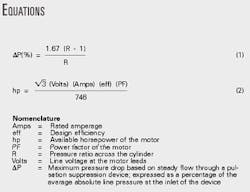
The pressure drop across a pulsation damper is based on a percentage of the average pressure at the inlet to each damper. Equation 1 (see accompanying equation box), from API 618, Section 3.9.2.2.4, calculates the maximum pressure drop.
The maximum pressure drop across a pulsation damper for the refiner's compressors was 0.92% and occurred in the second stage. In the original compressor design calculations, the OEM used a 1.0% pressure drop for all the dampers, which is consistent with the maximum allowable pressure drop calculated from Equation 1.
For the rerate calculations, however, the OEM used 2.5% of design pressure based on uncertainties in baffle integrity and vessel cleanliness and conservatism in the required horsepower calculation.
Once the potential rerate flows were calculated with the 2.5% assumed pressure drops, the OEM's analog engineering department compared data from an original analog study with the new expected flows. The company determined that a complete analog study was unwarranted.
While there was some risk to this, experience justified the risk. Increasing the flow by 44.1%, however, requires a new pulsation study because the pulsation dampers would have to be changed to accommodate the new cylinders.
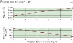
Fig. 1 illustrates the impact of pressure drop on flow and horsepower predictions.
Valve modifications
Unloader valves was one of the first considerations in the compressor rerate study.
These valves provide additional operating flexibility by loading and unloading the compressor in varying steps. Unloader valves have more fixed clearance than standard valves, however, reducing throughput.
There were seven suction-side unloader valves and one discharge-side, double-deck valve. The high-clearance, double-deck valve had been installed on the first-stage discharge to facilitate the installation of a clearance volume valve cap unloader located under the discharge valve.
The unloader under the double-deck valve provided the smallest change in the compressor flow rate, only 5%. Replacing this valve with a standard non-unloading plate valve reduced the first-stage fixed clearance, increasing gas flow through the compressor. This modification resulted in a flow rate increase of 1.7%, requiring an additional 50 hp.
Another compressor rerate option involved replacing all seven suction unloader valves with standard, non-unloader, plate valves. These valves unload the compressor in increments from 100% to 0% flow. They allow the machine to start up without the risk of interstage pressure buildup or excessive horsepower requirements.
Removing these valves would greatly restrict the compressor's operating flexibility, requiring expensive recirculation line from the third stage discharge to the first stage suction. The recirculation line allows startup of the compressor without the horsepower required for the fully loaded condition.
Removing all seven suction unloader valves from the compressor reduces operating flexibility and would only increase flow rate by 1.5%. This option, therefore, was not pursued.
Cylinder modifications
Enlarging cylinder bore sizes provided numerous, relatively inexpensive, possibilities to up-rate the compressor per the revised process conditions.
Most cylinders on reciprocating compressors are equipped with replaceable liners. The liners allow the cylinder diameter to be increased or decreased, within the design range of the particular cylinder class, to meet the revised duty requirements.
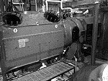
These liners usually have an interference fit in the cylinder body. Thus, the refiner removed the entire cylinder from the frame and took it into a machine shop for modifications (Figs. 2 and 3).
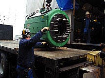
An existing liner can usually be bored to a larger diameter. If a cylinder must be smaller, the existing liner must be removed and replaced with a new one with the necessary interference fit. This requires heating the compressor body, or chilling the liner, or both.
By design, the cylinders in each of the three stages on the LM-3 machines could have bore sizes as large as 20.5 in., 17.75 in., and 11 in. to avoid a change in their cylinder class sizes. Only the third-stage cylinders were at their maximum size.
Initially, the refiner opened the first-stage cylinder liner bore in the first compressor from 19.5 in. to 20.0 in., a 6.8% increase in flow rate, to make incremental changes in the compressor flow rate. It also bored the cylinder liner on the second compressor to 20.5 in., a 12.4% flow rate increase.
During the review process, the team discovered the minimum liner thickness acceptable to the OEM was more liberal than that suggested in API 618, Section 2.6.2.3. An engineering review deemed the justification for the discrepancy acceptable.
While, in theory, removing the liner and running on the original cylinder bore maximizes flow through the compressor, this option was not considered. Without the liner as a sacrificial wearing surface, a damaged cylinder bore for cylinders of these sizes has a high cost and long lead time.
Crankshaft balance
There is little latitude available for reusing the existing compressor piston when the cylinder bore is enlarged. The refiner purchased new pistons for both the first stage 20.0 in. and 20.5 in. cylinder modifications.
Increasing piston size increases the unbalanced forces and couples acting on the machine foundation. Internal design of the piston, its design or manufacturing technique (cast vs. fabricated), and the piston material can affect the reciprocating weight on a compressor.
The refiner chose multi-piece compressor pistons to replace the original first-stage, single-piece, cast-iron piston. Besides ease of maintenance, an advantage of the multi-piece piston is more controllable weight, even to the point of using different materials for the various sections.
During the piston-change evaluation, it is important to review and decide how to treat the compressor frame in the force-balance analysis: as a rigid body or as a flexible body. The original design of the compressors included frame flexibility in the design and analysis.
A flexible body analysis is more rigorous and complex and takes into account all the opposing forces and couples that may not necessarily completely cancel one another and influence the design.
For the 6.7% and 12.4% cases, the OEM considered the calculated design weight of the new larger multi-piece pistons vs. the original single piece piston. It concluded there would be no substantial change in the unbalanced forces and couples.
Since the existing foundations were adequately designed and in good condition, the OEM deemed that no further changes in reciprocating balance weight or crankshaft counterweight were necessary.
A more detailed analysis should be carried out for the future 44.1% increase option as it involves larger to changes to the machine.
Assumptions
It is important to understand the assumptions and safety factors that are used in various calculations.
The impact of pulsation damper pressure drop from an assumed 5% to 2.5% on flow and horsepower is notable (Fig. 1).
At the project's inception, the refiner provided the OEM with expected operating data for the rerate conditions. In its analysis, the OEM assumed some parameters to account for any unknowns and uncertainties in their compressor calculation model:
- 95% of operating suction pressure.
- 105% of discharge pressure.
- 5% pressure drop across the suction and discharge pulsation dampers (after discussion, this was changed to 2.5%).
- 3% safety factor.
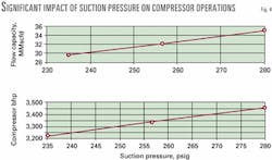
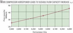
Fig. 4 illustrates the impact of suction pressure on capacity and horsepower. The impact of suction pressure on capacity can be significant. Fig. 5 shows the relationship between capacity and horsepower.
Motor design
Each compressor is driven by a synchronous motor rated at 3,500 hp, 300 rpm, 4,000 v, and 0.8 PF. These are the original motors installed in 1968.
API 618 Section 3.1.2.1 recommends the motor be sized to 110% of the compressor design horsepower. The 10% margin is a safety margin to account for design uncertainties in both mechanical equipment and process design.
Originally, the compressors were designed for 2,735 hp and, therefore, required 3,009 hp or larger motors. Thus, the next frame size motors, 3,500 hp, drove these compressors.
Compressor debottlenecking options requiring less than 3,150 hp did not raise any concerns about the motor size. Options that required more than 3,150 hp raised questions related to the API standard, safety, and reliability.
Along with a process review, the refiner conducted three independent methods to evaluate motor performance and reliability:
1. Winding temperature monitoring.
2. An on-line partial discharge test.
3. A polarization index test during compressor maintenance outages.
A first pass review easily determined where the motor was operating with respect to the original specified conditions. To evaluate the motor, the refiner plotted and analyzed motor winding temperature, amperage, horsepower, and various process data.
Data during a 2-year period showed that winding temperature increased with amperage as expected. The values were within acceptable levels of maximum allowable winding temperature rise and maximum amperage. Absolute winding temperature was also acceptable.
Westinghouse carried out an on-line partial discharge test to evaluate the motor integrity. The test found the motor insulation to be in good condition.
Off-line testing of the motor windings was another step to ensure the motor's electrical integrity. Polarization and winding resistance test resulting from past and recent inspections confirmed the motors were in good condition.
The refiner installed electronic equipment in both motors to allow on-line monitoring of motor condition.
After carefully reviewing API 618 and consulting with other compressor users, the project team concluded that there was no need to maintain the additional 10% horsepower margin. It was possible, therefore, to consider options that reduced the 10% horsepower margin.
The team decided to take a conservative approach and make small incremental changes to compressor capacity and closely monitor the results.
Power factor
The original motor PF was 0.8. Changing the PF to 1.0 would allow the motors to operate at 125% of the original nameplate, or 4,375 hp, with no capital investment in the motor and minimal capital investment in the electrical utilities.
Increased motor horsepower was necessary to increase the compressor flow by 44.1%.
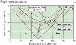
Point A in Fig. 6 denotes where the motor was originally designed to operate, 100% full load amperage at 0.8 PF. By adjusting PF, motor operation at full load moves down the "full load" curve to the "unity PF" line at point B. The motor now draws only 80% of full load amperage.
Along the "unity PF" line, Point C represents loading back to 100% full amperage. Here, the motor runs at a 25% higher than rated horsepower of 3,500 hp at 1.0 PF.
Equation 2 expresses this increase in horsepower.
The extra horsepower has penalties. For the subject motors, it reduces the pullout torque by 20%. Furthermore, the change in the PF requires the installation of additional capacitors to maintain the refinery overall power balance.
The motor OEM confirmed the potential for an additional 25% of original nameplate horsepower output by changing the motor PF to unity.
Other options considered to increase the motor rated horsepower included adding additional copper to the stator windings, increasing rotor size, and increasing the insulation grade.
Process equipment
The project team evaluated the design limitations of the associated process equipment affected by the increase in compressor capacity. The equipment included heat exchangers, knockout drums, cooling water headers, and process headers.
Pressure drops and flow velocities for the equipment were adequate and acceptable for the 6.7% and 12.4% flow rate increase options.
The study identified limitations on the water side of the first-stage intercooler, however, for the 44.1% flow rate increase option. The required increase in water flow rate resulted in an unacceptable pressure drop across the exchanger and required a larger or additional exchanger.
The team also reviewed cooling-water requirements for the compressor cylinder water jackets. The existing exchanger could handle the additional heat of compression for the short-term compressor rerate options. A compressor rerate with a greater than 12.4% increase in flow rate, however, would require additional cooling capacity and a larger exchanger.
Reference
- American Petroleum Institute, Standard 618, "Reciprocating Compressors for Petroleum, Chemical, and Gas Industry Services," 4th Edition, June 1995.
The author

Shailendra K. Gupta is a project team leader at the BP Whiting, Ill., refinery (formerly BP Amoco), responsible for managing major capital projects. Prior to his current assignment, Gupta was responsible for reciprocating compressors. He has more than 15 years of experience in the industry. Gupta holds a BSc in mechanical engineering from the University of Detroit. He is a registered professional engineer in Alberta, Canada.