Pitting, tensile overloading produce most coiled-tubing failures
A survey of coiled-tubing failures in various field applications shows that pitting and tensile overloads induce the greatest number of coiled-tubing failures.
Fatigue and weld area failures incurred the next most common type followed by H2S and brine-water corrosion.
Most failures occurred at well depths between 5,001 and 10,000 ft (1,524.3 and 3,048 m). Also, most failures occurred in the coiled-tubing string near the surface. Failures in roughly similar numbers were reported in grade types 70, 80, and 100.
The understanding of the principal modes of failure reported below should help improve handling and running procedures to minimize coiled-tubing failures.
The 30 case studies discussed include information on failure type, number of strain cycles to failure, service environment, well depth, failure location on the coiled-tubing string, and coiled-tubing grades employed.
Developments
Coiled-tubing technology has been employed for more than 30 years (OGJ, Jan. 10, 2000, p. 29). The primary areas of use are in oil field drilling, logging, workover, and production.1
Because of its cost effectiveness, the use of coiled tubing has expanded substantially in recent years. The development of stricter manufacturing process controls, as well as the development of steels with improved performance characteristics, have aided in the widespread use of coiled-tubing technology.
One of the most recent developments includes introduction of API RP 5C7, which dictates quality-control measures for the use of coiled tubing.2 In spite of all of these developments, significant concerns remain about the serviceability of coiled tubing in increasingly demanding environments.
As part of a continued effort better to understand and delineate operating limits for coiled tubing, a joint industry program (JIP) was carried out by InterCorr International Inc. The sponsors included major oil companies, equipment manufacturers, and material suppliers.
One of the specific objectives of this JIP was to conduct a survey of coiled-tubing uses and failures. Failures have a considerable economic impact both in terms of repair and replacement costs and additional costs associated with downtime.
The importance of the survey was to characterize the nature of coiled-tubing failures and to develop a better understanding of the failure rate and their causes.
Review
The subjects of failures and inspection advances performed during the manufacturing process and service operation have been examined.3 4 Smith and Misselbrook compiled failure information from industry databases and identified six general types of failure including mechanical, fatigue, corrosion, operator error, material, and manufacturing.
Similarly, Stanley identified the primary failure types, from field-collected information, as corrosion, damage caused by operator error, manufacturing, welding, wear and erosion, and low-temperature-induced brittleness.
Specific details about the failures are not given, however, except in the work conducted by Stanley in which some case histories are discussed.
Survey results
The following failure categories were ascertained from the survey responses received: fatigue, localized corrosion (pitting), general corrosion (uniform mass-loss corrosion), sulfide stress cracking (SSC) and stress corrosion cracking (SCC), tensile overload, helical buckling, mechanical damage, and welding.
The separation of failure types was not as straightforward as it may seem because more than one failure category manifested in a number of cases (i.e., weld area and tensile overload; pitting and fatigue).
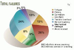
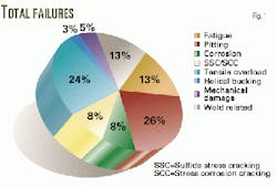
Fig. 1 presents the failure-type results obtained from the survey. On a percentage of total failures, the most prevalent types of failure were related to pitting and tensile overload. Exactly 50% of the failures documented in this survey resulted from pitting (26%) and tensile overload (24%).
Furthermore, corrosion-related failures accounted for 42% of the failures as follows: 26% pitting, 8% general corrosion, 8% SSC and SCC.
It should be noted that in the case of tensile overload, the numbers observed might be the result of the inherently high tensile loads to which the string is exposed. Operator error could also be the cause for this type of failure if the string is used outside of its safe operating limits.
Typically, a good safety margin for tensile loads should not exceed 80% of the specified minimum yield strength. Also, wall thinning resulting from general corrosion processes (uniform mass-loss corrosion) can effectively reduce the load bearing capacity of the coiled tubing.
At high operating temperatures and flow rates, reductions in wall thickness of as much as 80% have been documented after retrieving the coil from the well bore.3 Pitting can also produce a significant stress concentration in axial tension.
Fatigue and welds
The second most prevalent types of failure reported were fatigue (13%) and weld-related failures (13%). In recent years, fatigue failures have decreased dramatically due to better understanding of fatigue mechanisms and computer modeling.
Similarly, keeping precise cycle life records of the work string can minimize fatigue problems by retiring the string after its useful life limit has been reached. However, the synergistic effect of strain cycling and the corrosivity of the environment severely affect the performance of coiled tubing.
The presence of a corrosion environment can significantly reduce the fatigue limit of the material as localized corrosion within cracks plays an important role in fracture propagation and the reduced number of cycles to failure.1 Pitting can also serve as stress concentrator that might lead to crack nucleation.
Finally, welds are a natural location for stress concentration and microstructural anomalies, especially, when field butt welds are employed.5 Mechanical damage, which is generally introduced during coiled-tubing operations, was reported in 5% of the failures.
In contrast, in the work conducted by Stanley, operator error and corrosion accounted for 35% and 41% of the damage, respectively. 4 Manufacturing was the third most prevalent cause at 15%.
Strain cycles
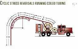
On a standard coiled-tubing round trip from which the coiled tubing is injected into the well and then retrieved, the material undergoes three bending cycles.
First, the coiled tubing is unspooled (Fig. 2). Second, it is bent around the tubing guide. Finally the coiled tubing, on the way back, is bent once again around the tubing guide where it is finally recoiled. Therefore, one bending cycle occurs at the reel and two at the tubing guide.6
Four different strain cycle ranges were designated as follows:
- Less than or equal to 10 strain cycles.
- Between 11 and 50 strain cycles.
- Between 51 and 100 strain cycles.
- More than 100 strain cycles.
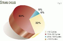
Fig. 3 shows the results for this particular category. As observed, most failures (63%) occurred in the range of 11 to 50 strain cycles. This particular fact correlates well with experimental observations where it was determined that many changes that occur in coiled tubing are observed within the first 10 strain cycles.
Therefore, by the time a particular location is cycled 10 times, it may have incurred a significant change in mechanical properties. This is usually manifested in terms of reduced yield strength and in some cases reduced tensile strength.
During cycling, the coiled tubing is deformed plastically from tension beyond the yield point and subsequently reloaded in the opposite direction under compression. It has been shown that after such cycles, the yield strength in the axial orientation can be reduced below the original yield strength of the material.
This dependence of yield strength on loading path and direction is commonly referred to as the Bauschinger effect and typically results in reduced yield strength without appreciable change in tensile strength, reduction in area, or elongation.7
Based on these observations, it would not be difficult to rationalize that in the range of 10 to 50 cycles, in many applications, fatigue failures may start to become more prevalent, particularly in combination with pitting corrosion or other stress concentrators.
Another trend in the survey data was that no high-cycle failures were reported (more than 100 strain cycles). The lack of reported high-cycle failures is probably not due to the lack of occurrence, but instead a lack of reporting since many operators retire older coiled-tubing work strings before failure occurs.
Once again, maintaining complete records of the number of cycles that a particular work string undergoes is extremely important.
Service environment
Eight different types of service environments were reported:
- Brine-water.
- Acid-inhibited HCl and HF.
- H2S.
- N2.
- Crude oil.
- Cement.
- Atmospheric-stored on reel prior to use.
- Geothermal.
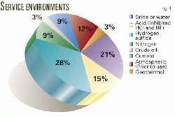
These service environments are representative of oil field drilling, logging, workover, and production environments in which coiled tubing is now employed (Fig. 4). In many cases, more than one service environment was identified in this survey.
This is particularly true for workover applications. The two most prevalent categories involved in failures included H2S (28%) and brine-water (21%). Highly corrosive environments, such as workover and completion environments, where highly concentrated brines (high specific gravity) are involved, generally produce high-corrosion rates since inhibitor solubility in this type of brine is extremely low.
The combination of severe corrosion in these applications, the possibility for general and localized corrosion (pitting), hydrogen charging, and loss of tensile capabilities or fatigue resistance is high in these environments.
The next most common environments to produce failures consisted of inhibited acid (15%) and atmospheric exposure (12%). Atmospheric exposure failures could be considered somewhat surprising since atmospheric exposure of conventional tubulars is not normally considered severe.
In cyclic applications, however, where coiled tubing is stored on the reel prior to service or between jobs, the combination of exposure conditions involving an aerated aqueous phase and possibly other corrosive species can be severe. Such conditions have been identified to have the ability to produce highly localized corrosion (crevice and pitting).
Highly localized attack can also serve as sites for stress or strain concentration, exacerbating tensile overload or fatigue damage. Both Sas-Jaworsky and Stanley have discussed the importance of appropriate operating procedures applicable after coiled-tubing retrieval for the prevention of corrosion.4 8
Well depth
The well-depth categories analyzed in this study were:
- Less than 5,000 ft (1,524 m).
- 5,001 to 10,000 ft.
- 10,001 to 15,000 ft.
- Greater than 15,000 ft.
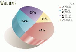
As Fig. 5 shows, failures were reported in all well-depth categories. Most of the failures were reported in the 5,001 to 10,000 ft category(41%). This category was followed by the 10,001 to 15,000-ft interval (24%) and the greater than 15,000-ft interval (24%).
The fewest failures were reported in the less than 5,000-ft category. This trend may be the result of two factors: increasing frequency of failure with increasing well depth or a high frequency of coiled-tubing wells occurring at intermediate depths.
It is expected that both tensile and fatigue effects would increase in severity with increasing well depth as a result of increased axial loads.
Failure location
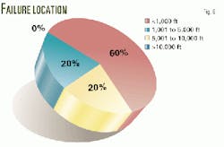
The failure location on the string categories included the following categories (Fig. 6):
- Less than 1,000 ft (304.8 m).
- 1,001 to 5,000 ft.
- 5,001 to 10,000 ft.
- Greater than 10,000 ft.
The most frequent location for failure in the coiled-tubing work string occurred at the top of the well bore shallower than 1,000 ft (60%)-typically below the well head or surface casing. The likelihood of failure would generally increase with axial loading of the coiled-tubing string.
The other two categories were split 20% each in terms of failures reported.
Coiled-tubing grades
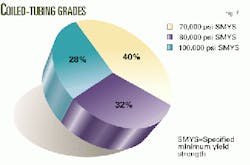
Three different grades were reported for coiled-tubing grades (Fig. 7):
- 70 Grade-70,000 psi (482.6 MPa) specified minimum yield strength.
- 80 Grade-80,000 psi specified minimum yield strength.
- 100 Grade-100,000 psi specified minimum yield strength.
The results indicate that of the failures reported, failures were relatively evenly distributed by coiled-tubing grade with a slight decrease with increasing strength level. Of the failures, 40% were 70 Grade material, 32% were 80 Grade, and 28% were 100 Grade.
No specific reason could be identified for this behavior. However, the decrease in the failure percentage with increasing yield strength, may be due to the increased resistance to tensile overload.
Future work
As the areas of coiled-tubing service expand to increasingly demanding and at the same time highly corrosive environments, a more comprehensive understanding of the synergistic effect of strain cycling and the corrosive environments is needed.
This will help to minimize their impact upon the serviceability of coiled tubing under those conditions.This aspect was investigated in a Phase II JIP, which is near completion.
References
- Kane, R.D., and Cayard, M.S., "Corrosion Degradation Mechanisms in Coiled Tubing," NACE International Corrosion/94, Paper No. 68, Houston, 1994.
- API Recommended Practice for Coiled Tubing Operations RP 5C7, First Edition, Washington DC, American Petroleum Institute, 1997.
- Smith, L., and Misselbrook, J., "An Overview of Inspection Technology and Criteria for Inspecting Coiled Tubing," SPE paper 38413 presented at the 2nd North American Coiled Tubing Roundtable (International Coiled Tubing Association) held in Montgomery, Tex., Apr. 1-3, 1997.
- Stanley, R.K., "An Analysis of Failures in Coiled Tubing," SPE paper 39352 presented at the IADC/SPE Drilling Conference held in Dallas, Mar. 3-6, 1998.
- Kane, R.D., and Cayard, M.S., "Factors Affecting the Serviceability of Coiled Tubing," Petroleum Engineering International, January 1994.
- Brown, P.A., and Dickerson, J.L., "Development and Use of an Analytical Model to Predict Coiled Tubing Diameter Growth," SPE paper 38409 presented at the 2nd North American Coiled Tubing Roundtable (International Coiled Tubing Association) held in Montgomery, Tex., Apr. 1-3, 1997.
- Cayard, M.S., and Kane, R.D., "Final Report: Serviceability of Coiled Tubing for Sour Oil and Gas Wells," Joint Industry Program Sponsored Research, InterCorr International Inc., Houston, 1994.
- A. Sas-Jaworsky II, World Oil, December 1991, p. 71.
The Authors
Julio G. Maldonado is manager of the technical services division at InterCorr International Inc. He specializes in materials selection and qualification of materials, failure analysis, and corrosion testing. He has more than 8 years of experience.
Maldonado holds a BS in metallurgical engineering, an MS in metallurgical and materials engineering, and a PhD in materials science and engineering from the University of Texas at El Paso (UTEP). He is a member of AIChE, ASM International, and NACE International.
Michael S. Cayard is currently vice-president of InterCorr International Inc. He provides consulting services to a wide range of industries, specializing in materials selection for corrosive service, field and laboratory evaluations, failure analysis, and fitness-for-service evaluations.
Cayard received his BS and MS in mechanical engineering and PhD in engineering mechanics and materials from Texas A&M University. He is a member of NACE, ASM, ASTM, and API.
In 1998, Cayard received the NACE International A.B. Campbell Award.
Russell D. Kane is president and founder of InterCorr International Inc. He specializes in materials specifications, field and laboratory evaluation, software development, equipment manufacturing, and failure analysis. Additionally, Kane is experienced in the use of steels, stainless steels, and other corrosion resistant materials.
He holds a BS, MS, and PhD in metallurgy and materials science from Case Western Reserve University in Cleveland, Ohio. Kane is a member of NACE, ASM, and ASTM.
This article was adapted after a paper presented at the NACE International 54th Annual Conference and Exhibition-Corrosion/99, San Antonio, Apr. 25-30, 1999.
