Tight schedule prompts staged start up for Viet Nam's first gas plant
A very tight project schedule for which all equipment could not be supplied by the targeted start-up date led to a novel stepwise completion of the first natural gas-processing plant in Vietnam.
The plan allowed for three successive modes of operation, each mode building on the previous one. When the plant reached full operation, the alternative modes remained in place to function as back up for the plant's rotating equipment.
In the first operating mode, ejectors were used for compression of process gas rather than a gas compressor because the compressor could not be supplied in time.
Sometimes referred to as a "jet compressor," an ejector uses high pressure gas as a motive fluid to compress a lower pressure gas. The exhaust of the ejector is at a pressure somewhere in between the two gas pressures.
The high-pressure gas discharges through a nozzle to the medium pressure, creating a lower pressure zone behind the nozzle that draws in the low-pressure gas.
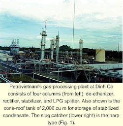
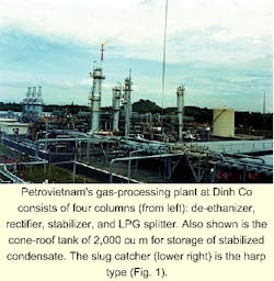
The Petrovietnam plant, in Dinh Co, Vietnam, about 100 km southeast of Ho Chi Minh City, reached full operation in May 1999 (Fig. 1).
Bach Ho supplies
Associated gas from the Bach Ho (White Tiger) field in Vietnam, about 100 km offshore, flows through a 16-in. submarine pipeline and is treated by the new gas-processing plant to recover LPG and heavier hydrocarbons with the residue gas used as fuel for two power stations.
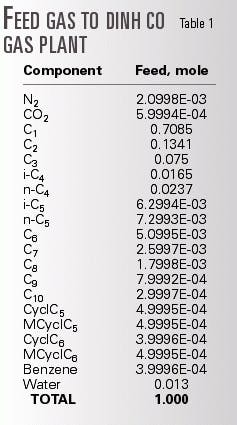
This is the first gas plant for LPG recovery in Vietnam. Table 1 presents the feed-gas composition to the plant.
The gas plant is designed ultimately as a turbo-expander process to recover 540 tonnes/day (tpd) of propane, 415 tpd of butane, and 400 tpd of condensate from an inlet gas flow of 1.5 billion standard cu m/year (bcmy; 4.3 MMscmd, 150 MMscfd).
The liquid products are sent to a remote LPG storage terminal through three 6-in. pipelines.
The plant consists of slug catcher at the plant inlet, molecular-sieve dehydration, cryogenic heat exchanger, turbo expander, gas-liquid separation, recompression of the residue gas, de-ethanizer, compression of de-ethanizer overhead gas, stabilizer, LPG splitter, product storage, and supporting utilities and offsite facilities.
Several features affect the process configuration.
One is the high inlet-gas pressure, as high as 109 bara, that results from the offshore compression for a common lift gas and sales-gas system. The lift gas requires the high pressure.
The pressure at the plant outlet is only 47 bara, the delivery condition of the sales gas to the pipeline. The large difference in the pressure at the inlet and outlet is the driving force for the process.
Another important factor is that the feed gas is associated with offshore oil production. The highest priority was maintaining oil production. Thus, the gas plant must accept all the gas coming from offshore.
The next priority was continuous gas supply to the power stations. The third priority was liquid product recovery.
Given these features, it is easy to understand why spare equipment should be provided for maximum reliability.
The process design to meet the required LPG recovery is an expander process that splits the gas stream into two parts, with one part going to the turbo-expander and the other part flowing through a gas-gas exchanger to provide column reflux. This concept appears in a number of processes offered by Ortloff Engineers Ltd., Midland, Tex.
The high pressure drop available across the plant negates the need for additional residue-gas compression beyond that provided by the expander compressor. This is also a unique feature of the process.
The most serious problem in the project was its very tight schedule for initial startup of processing: 101/2 months. There was no room for compromise because the offshore compression platform was operating and the gas-processing plant was needed to achieve the increased delivery of sales gas and production of salable liquid products.
It was quite obvious, however, that all the process equipment could not be installed within such a short period. The gas compressors and turbo expander needed more than a year for delivery.
This situation led to a design solution that involved three steps for plant completion: Three successive operational modes would allow revenues to be generated as soon as possible.
Modes of operation
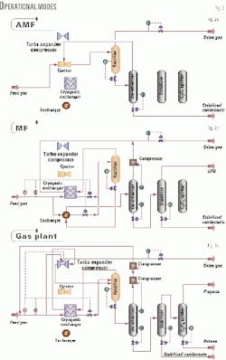
The first mode of operation is called the "absolute minimum facility" (AMF). Its main purpose is to supply dewpoint-controlled gas to the power stations (Fig. 2a).
Therefore, liquid recovery is minimal and only the stabilized condensate is recovered. All the LPG components are included in the sales gas.
It consists of two columns, three exchangers, and three vessels to recover 340 tpd of condensate.
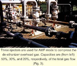
Ejectors rather than gas compressors are used (Fig. 3). Ejectors are well-proven equipment, very simple, inexpensive, and have a short delivery time. The AMF completion was within 101/2 months.
The second mode is the minimum facility (MF) whose main purpose is to recover condensate and mixed LPG liquid products with no expander (Fig. 2b). It consists of AMF plus an additional column, molecular-sieve dehydration, one reciprocating compressor of 800-kw driven by a gas engine, cryogenic exchanger, two exchangers, and three vessels to recover 630 tpd of mixed LPG (butane and propane), and 380 tpd of condensate. Its completion was within 14 months.
The final step, called the "gas-processing plant," maximizes liquid recovery (Fig. 2c). It recovers 540 tpd of propane, 415 tpd of butane, and 400 tpd of condensate.
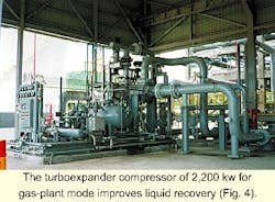
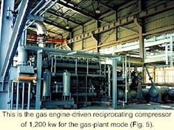
This mode consists of MF plus an additional 2,200-kw turbo expander, 1,200-kw reciprocating gas compressor driven by a gas engine to recycle de-ethanizer overhead gas to the plant inlet providing additional recovery, two columns, shell-and-tube heat exchangers, air-cooled exchangers, vessels, pumps, and other process equipment. Its completion was within 18 months.
In the AMF mode (Fig. 2a), the plant feed gas after the slug catcher is sent to the ejectors as the motive fluid, through which the gas pressure drops from 109 bara to 45 bara. Liquids are dropped out in the rectifier and the overhead gas flows to the power stations.
The ejectors compress the de-ethanizer overhead gas from 20 bara to 45 bara. Thus, flaring of the overhead gas can be avoided. The liquid hydrocarbon removed from the gas in the rectifier has the butane and lighter components stripped off in the de-ethanizer, which actually functions as a stabilizer in this operating mode.
In the MF operation (Fig. 2b), the gas is first dehydrated and then chilled in two heat exchangers. Both streams are expanded from 109 bara to 45 bara with Joule-Thomson (JT) valves and then fed to the rectifier to separate all the liquid condensed.
The gas separated in the rectifier is first used as a low-temperature source to chill the feed gas and then is sent to the power stations through the sales gas pipeline.
The liquid separated in the rectifier is sent to the de-ethanizer after it is used to chill the feed gas. In the de-ethanizer, ethane and lighter components are stripped from the liquid.
The operating pressure of the de-ethanizer is controlled at 29 bara by an additional compressor that sends the overhead gas to the sales-gas line. The stabilizer, an additional column, separates LPG at the top and stabilized condensate at the bottom.
In the gas-plant operation (Fig. 2c), the gas is first dehydrated and split into two streams. One stream is chilled in the cryogenic heat exchanger, let down through a JT valve, and fed to the top of the rectifier.
The other is expanded through an expander from 109 bara to 32 bara and flows to the bottom of the rectifier. It is only in the gas-plant operational mode that the rectifier acts as a true distillation column. In the other modes, the operating pressure is too high for effective distillation.
The gas separated in the rectifier is first used as a low-temperature source to chill the feed gas, is compressed by the expander-compressor from 32 bara to 45 bara, and finally sent to the power stations through the gas pipeline.
The gas from the de-ethanizer is sent back to the plant feed by an additional compressor to increase liquid recovery further. The C3/C4 splitter, an additional column, separates propane at the top and butane at the bottom.
Special considerations
The project concept as described includes several special features.
- Spare equipment. After the completion of gas-processing plant, the function of the three modes becomes different from the initial one.
In normal operation, the plant is operated under the gas-plant mode because maximum liquid recovery is generally preferred. Other modes would be applied only in the case of equipment shutdown.
When the turbo expander shuts down, for example, the operation could be changed to MF mode except that the recycle compressor would remain operating. This results in higher recovery than in the original MF operation.
When the reciprocating de-ethanizer overhead compressor shuts down, the operation could be changed to AMF with the ejectors taking over this service. The de-ethanizer would continue to operate at the higher pressure and some LPG would be recovered.
As a result, spare equipment for the turbo expander or reciprocating compressors is not provided. The plant can continue to run at reduced recovery without the spares by changing the operating mode.
- Commissioning. Common practice for safe startup of any hydrocarbon-processing plant is that feed hydrocarbon be introduced into the system only when all hot work is completed. The concept of the three modes, however, violates this rule. This was the greatest concern during the plant commissioning.
During commissioning of one mode, construction was occurring simultaneously elsewhere, creating a possibly dangerous situation. Several measures were applied to prevent an accident.
Almost all the line branches for the mode-change operation are isolated with blind flanges to avoid leakage. The equipment plot plan is so arranged that all the equipment of one mode is placed in a same area as much as possible.
- Change operation. The system is so designed that one operation mode can be manually switched to another without interruption of gas flow.
Several pieces of equipment are used for the three modes with different operating parameters. Typical is the de-ethanizer.
In the basic AMF operation, it functions as a stabilizer, with an operating pressure as low as 20 bara and a reboiler temperature as high as 192° C.
In the other modes, it operates as a real de-ethanizer under the conditions of 29 bara and 120° C.
These process parameters can also be changed without interruption of the gas supply.
- Ejector. Performance of the ejectors must be carefully considered in this application. The main concern is the rather narrow operating range.
The plant feed gas flow rate is determined by the oil production offshore, and the gas demand depends upon the electricity consumption at the power stations. The gas rate, therefore, fluctuates significantly.
Ejector compression capacity drops sharply with lower motive gas rate. A variable spindle-type ejector could be a solution for this plant turndown problem, but none of them available on the market could meet the process requirement.
The solution was to supply three ejectors; the capacities of each being 50%, 30%, and 20%. With combinations of these three, a wide range of the gas flow can be covered, from 20% to 100 %.
Ejectors have a low efficiency compared with an expander-compressor set, as low as 20 %. In this application, however, use is only temporary and as a spare; thus the effect of this disadvantage is minor.
The ejectors also were operating at the limits of their compression ratios in the AMF operation. This was why variable-spindle ejectors could not be used because the compression ratio was far greater than the limitation of that type of ejector.
Operation
The plant was commissioned successfully in October 1998 for AMF, in December for MF, and in May 1999 for gas-processing plant.
The mode change operations from AMF to MF and from MF to gas-processing plant took several hours without interruption of the gas flow.
The three ejectors functioned according to design and coped with the plant turndown problem.
The authors
Mamoru Omiya is a manager of process engineering at NKK Corp., Yokohama. He specializes in hydrocarbon processing design and project management. Omiya holds a BS and MS in chemical engineering from Tokyo Institute of Technology.
Junji Takahashi is a senior process engineer in the energy industries engineering division of NKK Corp. He specializes in process design and commissioning of natural gas processing plants and of district heating and cooling plants. Takahashi has more than 12 years of experience. He holds a BS and MS in chemical engineering from Yokohama National University.
Shin Kawamura is a senior process engineer of energy system engineering at NKK Corp. He specializes in hydrocarbon processing design. Kawamura holds a BS and MS in chemical engineering from Yamagata University.
James M. Sherman currently is an independent consultant employed as the facilities manager for Harrods Energy (Thailand) Ltd., Bangkok. Previously, he was Brown & Root's process engineer on the consultancy contract with Petrovietnam for the Gas Utilization Project, which included the Dinh Co gas-processing plant. Sherman is a 1969 chemical engineering graduate of the University of Nebraska and a member of AIChE.
Sang Won Lee is a manager of project department in Samsung Engineering Co. LTD., Seoul. He has worked as project manager, engineering manager, and procurement and design engineer. Lee holds a BS in electronic engineering from Sungkunkwan University, Korea.
