Qatargas upgrades, debottlenecks Ras Laffan LNG plant
The Qatar Liquefied Gas Co. Ltd. (Qatargas) is currently expanding and debottlenecking its Ras Laffan LNG plant. This article describes the overall scope of the debottlenecking project and what has been accomplished to date.
The LNG plant was originally designed to produce 6 million tonnes/year (tpy) of LNG, which is delivered to a consortium of Japanese buyers led by Chubu Electric Power Co.
When completed in 2005, the debottlenecking project will increase actual production to more than 9.5 million tpy with a total engineering, procurement, and construction cost of about $185 million.
Qatargas is implementing the plant modifications in steps and train-by-train during planned train major overhauls.
The project's first step, which only consisted of upgrading the Train 1 mixed-refrigerant (MR) gas turbines, was completed during the 2002 major overhaul. Step 2 was successfully completed in October 2003 with the full debottlenecking of Train 2 and plant-related utilities.
null
Qatargas project background
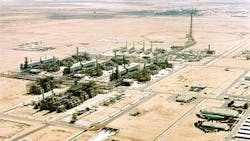
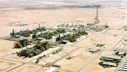
The Qatargas LNG plant (Fig. 1) is part of the second development phase for the North field gas resources in Qatar.
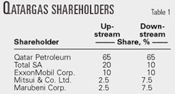
Located at Ras Laffan, the plant is owned and operated by Qatargas, a joint venture between Qatar Petroleum, Total SA, ExxonMobil Corp., Marubeni Corp., and Mitsui & Co. Ltd. (Table 1).
Raw gas and field condensate produced offshore move via a 32-in. OD, 80-km long pipeline to the shore where approximately 50,000 b/d of condensate are separated from gas, stabilized, and stored before shipment.
The gas feeds three identical gas treating and liquefaction trains; produced LNG is stored in four 85,000 cu m, double-containment tanks. All these facilities are supported by common utilities and offsite facilities. Details of the existing plant have already been reported (OGJ, Aug. 24, 1998, p. 41).
LNG production started in late 1996 from Trains 1 and 2; Train 3 was commissioned in 1998. Each train was designed for an average production of 2 million tpy of LNG. Soon after start-up, however, it became clear that the plant could produce much more with limited upgrading.
In early 1999, Qatargas launched feasibility studies with KBR, a subsidiary of Halliburton, covering offshore and onshore facilities to identify the debottlenecking requirements for various production levels.
Based on the results, Qatargas decided to increase the production capacity to 9.2 million tpy of LNG (loaded on ship). Based on the 2002-03 performance test results from Trains 1 and 2, the production capacity was recently revised upward to 9.5 million tpy.
After the completion of these LNG feasibility studies, KBR completed the front-end engineering and design work in June 2001; the engineering, procurement, and construction contract was awarded to a Chiyoda Corp. and Technip joint venture (CTJV) in October 2001.
In 2000, Technip completed the debottlenecking of the offshore facilities.
Project scope
The LNG debottlenecking project includes the three LNG trains, some utility systems (steam, fuel gas), and the onshore upstream facilities. The project will increase the capacity of the LNG storage and loading systems' boil-off gas compression; other general facilities are unchanged.
The onshore upstream facilities receive the dewatered wellhead production through the offshore pipeline (dry transportation scheme). These facilities include a slug catcher, condensate stabilization, and offgas recompression. Only the gas knockout drums were debottlenecked; the internals were changed to maintain adequate phase separation.
The conventional LNG train includes:
- Sulfinol acid-gas removal (H2S, CO2, and mercaptans).
- Dehydration and trace sulfur removal with molecular sieves.
- Mercury removal with a sulfur-impregnated carbon (upstream of acid gas removal and downstream of dehydration).
- Refrigeration and liquefaction with the Air Product and Chemicals Inc. C3-MR process.
- NGL fractionation to produce a makeup stream for the refrigeration cycles.
- A nitrogen-removal unit to treat the LNG before storage.
Most of the modifications required to reach the targeted production are in the refrigeration unit—primarily upgrading and replacing the refrigerant compressors and gas turbine drivers.
Outside the refrigeration unit, only a few items must be upgraded:
- Drier precooler separator: modification of internals.
- Scrub column: modification of trays and inlet device.
- Scrub column reflux drum: modification of internals.
- LNG product pump (rundown): replacement of impellers and electric motor driver.
- De-ethanizer: modification of trays.
The two sulfur-recovery units, common to the three trains, require no modification.
Refrigeration cycles
The capacity increase results from more refrigeration power, i.e., greater refrigerant flow rates for both the precooling and MR cycles. This implies that more power is needed from the gas turbine drivers via upgrading the existing gas turbine for the MR cycle and adding a new gas turbine in the propane cycle.
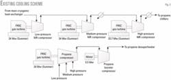
Fig. 2 shows the original refrigerant compression scheme. MR compression includes three centrifugal compressors—low, medium, and high pressure—each driven by a General Electric FR5C gas turbine.
Propane compression includes a three-stage centrifugal compressor driven by a GE FR5C gas turbine and an electric-motor-driven booster used only during the summer when the propane condensing temperature is high. General Electric Co.-Nuovo Pignone, Florence, supplied these machines.
For the debottlenecking project, Qatargas awarded a contract directly to GE-Nuovo Pignone in 2001 to upgrade or replace the gas turbines and compressors. The contract was later assigned to CTJV.
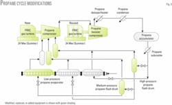
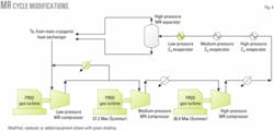
Figs. 3 and 4 show the refrigerant system items that were modified, replaced, or added.
In the MR cycle, each FR5C is upgraded to an FR5D, which can provide 13% more power. The three MR compressors are modified with new impellers in the existing casings so the power of the MR cycle increases 26%.
The propane cycle received a new three-stage compressor driven by a new FR5C gas turbine. To cope with the large suction volume flow rates, a gearbox is added to reduce the nominal speed to 3,400 rpm from 4,670 rpm. The booster compressor is also replaced, driven by an existing FR5C.
Because the original propane booster compressor could be dismantled without stopping LNG production, its location is used for the new main propane compressor in each train. This minimizes overall down time and loss of production.
The total power of the propane cycle increased 78%.
Several refrigeration unit compressor suction drums required modification of the internals to accommodate the larger refrigerant flow rates. The low-pressure MR recycle cooler was also replaced with a new heat exchanger.
Changing the balance of duties between the three levels of propane vaporization allowed the propane kettles to remain unchanged, except the MR low-pressure propane evaporator. New propane flash drums, however, were added at the high and medium-pressure levels to reduce the vapor flow through the kettles.
The MR low-pressure propane evaporator duty increases 13% and the cold-side temperature approach decreases to 1.5° C. from 3.0° C., which is lower than usual and implies a large exchange area. Because this exchanger is part of a chilling train with a tubesheet-to-tubesheet arrangement, the number of tubes cannot be changed.
To achieve this low-temperature approach and minimize the new tube length and space requirement, CTJV decided to use special tubes developed by Wieland-Werke AG, Ulm, Germany.
The Wieland PB4 double-enhanced tubes are effective for hydrocarbon vaporization and are well adapted for LNG plant chillers. The tubes were previously tested in a C3 splitter reboiler, designed by Technip, for the Targor (a joint venture of BASF AG and Hoechst AG) polypropylene plant, Knapsach, Germany. Test runs on Qatargas Train 2 confirmed tube performance with a temperature approach of 0.9-1.0° C. compared to the specified 1.5° C.
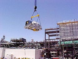
In a delicate operation, the new main propane compressor was lifted while the train was still operating (Fig. 6).
Utilities
Qatargas modified the fuel-gas system to improve the quality of fuel gas feeding the gas turbines.
There are three sources of fuel gas: end-flash gas from the nitrogen removal unit, boil-off gas from the LNG tanks, and makeup gas from the feed gas to the trains.
To increase the heating value of the fuel feeding the turbines, boil-off gas is used preferentially for power generation; remaining gas feeds the turbines in the trains. End-flash gas first generates steam; the remainder feeds the train's gas turbines. High heating value makeup gas from the feed gas is used to balance the mechanical drive.
A new fuel-gas mixing drum was also added to keep the rate of change in heating value below a maximum acceptable level for the gas turbines (0.15%/sec).
The steam-generation unit has sufficient capacity for the debottlenecked plant. The change in fuel-gas quality, however, forced modifications for the piping, control valves, and burners in each boiler.
Project status
Qatargas is implementing the LNG debottlenecking project in steps. These steps are aligned with scheduled inspection and maintenance periods for each train (major overhauls). Debottlenecking work on each train is conducted in 33 days (45 days LNG to LNG).
null
The first step, which included only upgrading the Train 1 MR gas turbines from FR5C to FR5D, was completed in 2002.
The second step, which included the full debottlenecking of Train 2, was successfully completed during the September-October 2003 shutdown. This allowed LNG production to resume on schedule with a better-than-expected increase in capacity. Modifications to the utilities and fuel-gas system in Train 2 were also completed during this period.
A fourth boil-off gas compressor was also installed during this time.
The next steps that will include debottlenecking Trains 3 and 1 will occur in 2004 and 2005, respectively.
Project execution
Such a project placed a large focus on construction; the project management team was brought to the site as early as possible.
Before that, the detailed engineering work was conducted in Technip's Paris offices after a short period during which Chiyoda conducted additional front-end engineering activities in its Yokohama offices. This was done to capitalize on Chiyoda's knowledge of the existing plant, which it designed and built.
During this initial period, the project management team was located in Paris to organize the detailed engineering and procurement under the guidance of the Qatargas project management team.
Much of the work was allocated to Nuovo Pignone to upgrade and change the LNG train compressors and turbines.
CTJV assigned a permanent representative, along with a Qatargas representative, to the Nuovo Pignone facility in Florence to monitor and inspect the equipment during manufacturing.
CTJV selected a construction subcontractor that specialized in revamp work and was already acquainted with the Technip revamp-work management methodology that was implemented on an earlier project in the Middle East.
During the project's initial phase, Qatargas and CTJV used videoconferencing facilities to ensure smooth coordination between the parties at the working level. In addition, monthly management meetings were held on site with Qatargas and the construction subcontractor and at Nuovo Pignone's workshop.
A constructibility review was conducted during the detailed engineering period to optimize planning, design, procurement, and field operations to achieve overall project objectives, maximize safety for field activities, and optimize overall project costs and scheduling.
One objective of the review was to minimize the amount of work during the shutdowns and to maximize preshutdown work because restricted space and limited time were available for shutdown activities. The debottlenecking project had to consider that major overhaul maintenance and plant works not included in the project scope had to be performed by other dedicated contractors.
The project focused on identifying critical preshutdown activities and creating maximum opportunities to reduce the shutdown work by performing extensive tie-in work before the shutdown.
Under the lead of the construction-planning manager, a small team that included engineering, construction, and commissioning workers was formed to establish a work list used as the basis to generate the preliminary list of job cards.
A job card is a work-package system that contains the applicable documents and lists of the required materials and construction resources for each activity, including a job safety analysis.
All construction activities were divided into job cards to allow a comprehensive and detailed planning of the construction work. For Train 2 preshutdown and shutdown activities, approximately 1,000 job cards were prepared.
Site activities
In February 2004, the project reached 60% of site work physical progress and 3 million man-hr without a lost-time accident.
Train 2 preshutdown activities
The preshutdown activities for the first train major overhaul (Train 2) and the construction of the new boil-off gas compression unit began in July 2002 and mobilized an average of 500 multinational workers and 200 indirect personnel from CTJV, Nuovo Pignone, and construction subcontractors.
Other locally established companies were also involved to a lesser degree in the debottlenecking work. The work force's size will vary to meet the site requirements until the project is completed in summer 2005.
To achieve the successful debottlenecking of Train 2 with a short schedule (Sept. 18 to final handover on Oct. 25), CTJV mobilized 1,200 persons on a double-shift system.
The debottlenecking project team was integrated into a Qatargas shutdown team, which was involved with the debottlenecking project scope of work and various engineering and maintenance activities.
Maintenance work required an additional 350 persons during the shutdown.
For the debottlenecking work—which included the installation of 350 tons of piping, difficult replacement of propane compressor and booster, and other modifications—a thorough preparation was completed in August 2003.
This was based on a systematic identification of each elementary work item (job cards), precise scheduling and sequencing, and a job safety analysis that complied with Qatargas safety policy.
Preparation work is now in progress for the Train 3 shutdown, scheduled for April-May 2004.
This includes an analysis and implementation of lessons learned from the Train 2 shutdown.
This "lessons-learned" system, put in place by Qatargas, was established for safety, scheduling, organization and coordination, and technical simplifications.
At the preshutdown stage, Qatargas emphasized the safety measures required for activities in an operating plant; all personnel attended training courses aimed at minimizing incidents, in a program known as the "Incident and Injury-free Initiative."
Through this program, the Train 2 shutdown was completed without a single lost-time accident with more than 1,200 persons working in a congested area.
In addition to the incident and injury-free initiative, other safety incentive programs are being applied to improve safety standards.
A regular draw is organized to reward individual contributions to the safety environment, and a specific safety incentive program has been implemented at the workman level during the shutdown.
One task during the preshutdown activities was the lift of the new main propane compressor over the pipe rack and compressor building while the train was in operation (Fig. 6).
Train 2 shutdown
After a final readiness review between all parties to fine-tune the procedures and coordinate activities, Qatargas operations gave the "go ahead" after the degassing phase was completed.
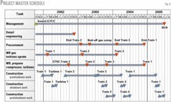
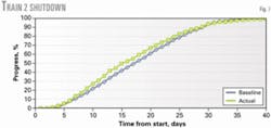
After matching the planned progress curve (Fig. 7), the last handover certificate was issued on Oct. 25, and LNG production resumed on schedule.
After Train 2 restarted, Qatargas and CTJV completed a performance test for train capacity and machinery performance in December 2003.
Results indicate that the capacity of the debottlenecked train is higher than expected, allowing Qatargas to increase nominal plant capacity to 9.5 million tpy.
Safety was a primary concern. Under the Qatargas incident and injury-free program and with the guidance of its safety department, Qatargas took specific precautions to eliminate hazards during preshutdown activities in an online plant. In particular, work permit and simultaneous operating procedures were revised to reflect project difficulties.
The authors
Bernard Duchemin is manager of the debottlenecking project for Qatar Liquefied Gas Co. Ltd., Doha. He also served as LNG technical manager for Total SA, Indonesia, and process group manager for Total SA, Paris. Duchemin holds a degree in chemical engineering from Caen University, Normandy, France, and an engineering degree from Ecole Nationale Supérieure du Pétrole (ENSPM), Rueil Malmaison, France.
Gerard Renaudin is chief technology officer for the LNG business unit of Technip, Paris. He has 30 years' experience in Technip's process and technology division. Renaudin holds a BS degree (1965) in chemistry from Grenoble University, France, and engineering degrees from L'Ecole Nationale Supérieure d'Electrochimie et d'Electrométallurgie de Grenoble (1966) and ENSPM (1967).
Moritaka Nakamura is general manager of the natural gas process engineering department for Chiyoda Corp., Yokohama, Japan. He joined Chiyoda in 1979 at its LNG receiving terminal, Japan, and then worked on overseas LNG liquefaction projects and most other major LNG projects for Chiyoda. Nakamura holds a masters degree (1979) from the Tokyo Institute of Technology.
