Successful drilling of lateral wells in minimum horizontal stress direction for optimal fracture placement
Zillur Rahim
Adnan A. Al-Kanaan
Hamoud A. Al-Anazi
Mahbub S. Ahmed
Saudi Aramco
Dhahran
Saudi Aramco is developing several gas fields in the Eastern Province of Saudi Arabia by drilling horizontal wells in the Khuff and pre-Khuff tight carbonate and sandstone formations. To date, many wells have been drilled in the maximum horizontal stress direction with virtually no wellbore instability occurring during the drilling operation.
When these wells are hydraulically fractured, the fracture grows along the wellbore in the direction of well azimuth. To avoid overlapping of two adjacent induced fractures and thereby communication between stages, only two to three multistage fracture treatments can be performed.
Depending upon the length of wellbore-reservoir contact, reservoir development, and stress barriers, more than four fracture treatments can become redundant or even cause premature screen-out in proppant fracture treatments.
Wells drilled in the direction of minimum horizontal stress are potentially more favorable from the perspective of reservoir development and optimal production. In such a situation, hydraulic fractures grow transverse to the wellbore axis allowing multiple fractures to be placed without the possibility of fracture overlapping. Consequently, few wells that have been drilled in the minimum horizontal stress direction encountered several drilling-related problems, such as stuck pipe, breakouts, and breakdowns.
A comprehensive study was conducted to overcome the wellbore stability issues and investigate feasibility of drilling wells in the minimum horizontal stress direction. Correct mud weight (MW) prediction is one key factor during the drilling stage to keep the wellbore stable and deliver good borehole geometry to run multistage fracturing assembly without complication. Multiple transverse hydraulic fractures easily created in such wellbore geometry maximize reservoir contact area and increase productivity of the low quality tight reservoir.
The key objectives of the study were to define a safe MW program for the horizontal section of the planned wells by conducting a wellbore stability study and to determine a real-time strategy to mitigate and-or manage wellbore instability problems as they arise. The scope of work included root cause analysis of drilling events, development of mechanical earth models (MEM) for offset wells, integrating sections of the MEM from the offset well to the planned well trajectory, and a safe MW program for planned well.
Introduction
Saudi Aramco has been successfully exploiting its gas reservoirs for the past decade with hydraulically fractured vertical and horizontal wells.1-6
Development of MEMs has allowed the optimization of drilling trajectory, completion mechanism, perforation interval selection, and fracture design.4-5 Current development strategy includes drilling horizontal wells and completing them with multistage fracturing.3
Numerous wells are drilled in the direction of maximum horizontal stress (σmax) to minimize risks associated with well integrity during drilling and production life. Most of the horizontal wells completed in relatively tight formations are often fractured for improved production.
Horizontal wells drilled toward the minimum horizontal stress (σmin) offer a better chance of higher production from fracturing.3 Hydraulic fractures induced in a wellbore parallel to σmin will be transverse (orthogonal) to the wellbore, thereby ensuring better reservoir contact with the formation and providing the possibility of inducing many fractures without compromising fracturing efficiency.
Although drilling toward σmin is preferred for placing hydraulic fractures, the drilling of the well itself may be challenging due to wellbore integrity and stability issues. This is because the wellbore is subject to higher stresses and thereby requires more MW to control breakdown or collapse of the formation.
A pilot program to drill toward σmin has already been initiated with much success. The drilling success depends mostly on how good the MEM can predict wellbore condition and associated control parameters such as MW.
Review of offset well drilling events
Drilling events are the most critical information to capture and understand to appropriately design a proper drilling program.
Many types of drilling events occur; among those are lost circulation, wellbore breakout or breakdown, tight sections, stuck pipe, well ballooning, etc. These events may be attributed to different causes such as formation deformation, induced fracturing due to improper MW, and encountering of high stress intervals. Overall assessment of offset wells helps in avoiding and overcoming potential problems that may occur while drilling.
At the same time, the identification and analysis of the drilling events related to geomechanics in the offset wells provide good calibration and validation data to make a first pass determination of the in situ stress direction and magnitude and thereby help constraining the MEM. Subsequently, as the well is drilled in the target reservoir, dynamic calibration and updates of the model is performed along with predictive MWs with the help of real time logging information.
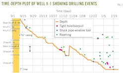
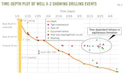
Two example wells are cited in this section. Figs. 1 and 2 illustrate the daily time vs. depth plots constructed using the drilling reports from Wells X-1 and X-2. The reports are screened and analyzed to show any important drilling events or occurrences. The time-dependent wellbore instability occurring across the argillaceous intervals in the pre-Khuff Unayzah formation is observed in Well X-2. In Well X-1, the stuck pipe event leading to sidetrack is most likely related to the drilling break. In the sidetracked hole (Well X-1), all the wellbore instability events in the Unayzah formation occurred after freeing the stuck pipe on 12/22. Relevant information was then used to perform a history match to validate the MEMs.
Mechanical earth model
The MEM is a numerical representation of the state of stress and rock mechanical properties for a specific stratigraphic section in a field or basin.
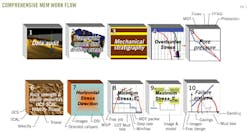
Fig. 3 presents the work flow to carry out a complete MEM analysis starting from data gathering and auditing to computation of rock stress and rock failure parameters. The model is linked to geologic structure through the local stratigraphy and a three-dimensional (3D) seismic cube. In its basic form, the MEM consists of depth profiles of the elastic and-or elastoplastic parameters, rock strength, and the earth stresses referenced to the local stratigraphic section.
Fig. 4 shows a one-dimensional (1D) representation of an MEM and links to the stratigraphy and 3D seismic cube. From left to right the profiles include: Poisson's ratio (v), Young's modulus (E), unconfined compressive strength (UCS), friction angle (Φ), pore pressure (Pp), minimum horizontal stress (σmin), maximum horizontal stress (σmax), vertical stress (σv), and the direction of horizontal stress axes. Lithologic variations in MEM parameters are governed by the mechanical stratigraphy.
Research has shown that rock strength and earth stresses profiles are modulated according to the nature of the dominant load-bearing solid phase. The mechanical stratigraphy is a bimodal textural model of a stratigraphic sequence.7 The bimodal classification differentiates rocks with clays as the dominant load-bearing solid from rocks with quartz or carbonate minerals as the dominant load-bearing solid. Petrophysical models are then used to transform the mechanical stratigraphy into elastic, elastoplastic, and rock strength profiles.
Lateral variations in mechanical properties, associated with geologic structure, are captured by linking the mechanical stratigraphy to a 3D framework model. The 3D framework model consists of surfaces, such as formation tops and faults. The surfaces are interpreted from seismic data, guided by log data and the geologist's lithostratigraphic model.
In its most complete form, the MEM consists of a full 3D description of pore pressure, stress, and mechanical properties. In practice, the complexity of the model evolves in step with the acquisition of new information.
From exploration to development, the model evolves from of a sparse set of 1D profiles to a full 3D description of rock properties and earth stresses. The degree of detail captured by the model will vary from field to field depending on the perceived operational risks.8
Therefore, the MEM is a logical compilation of relevant information about earth stresses and rock mechanical properties in an area, a means to update that information rapidly, and a plan for using the information for drilling operations and reservoir management.
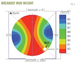
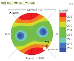
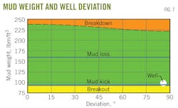
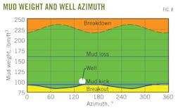
Figs. 5 to 8 illustrate some of the prediction from MEM where the MW values for breakout and breakdown and MW window as function of well deviation and azimuth are given respectively. The white dot on the figures is the position of our well, which is nearly horizontal and drilled in the N140E direction, close to the direction of σmin.
Figs. 5 and 6 show the well azimuth direction as well as wellbore deviation from vertical to purely horizontal. In the local stress regime which is strike-slip (σmin<σv<σmax) the hydraulic fracture plane is approximately E75N; for such a configuration, a higher MW is required to prevent breakout, Fig. 5, and lower MW is required to avoid breakdown, Fig. 6.
The MW windows shown in Figs. 7 and 8 indicate MW limits where either mud kick or mud loss can occur. Mud kick occurs as borehole fluid pressure falls below reservoir pressure and mud loss occurs when borehole fluid pressure exceeds reservoir pressure. Both these situations should be avoided for wellbore integrity.
The green zones (Figs. 7 and 8) indicate the safe area where neither breakout nor breakdown will happen; however, the optimum zone is in between mud loss and mud kick limits. For our reservoir and field characteristics, the rock strength is high and therefore the breakout stress is lower than the mud kick pressure.
Wellbore stability of offset and planned wells
The wellbore stability (WBS) analysis and MW predictions are based on comprehensive understanding of current drilling experiences, practices, and detailed calibration of MEM from offset well data.
The information is acquired from drilling and completion reports based on challenges and important events encountered during drilling and are classified into different categories for evaluation.
Based on the drilling experience for the given MW, in situ stresses, formation pressure, and the rock strength, a geomechanical model is developed. The model predicts downhole conditions such as breakouts, breakdowns, MW window, and induced tensile cracks.
Depending upon the stress state and formation properties, the breakouts and induced cracks may be present or absent. In addition, if they exist, their severity may change along wellbore trajectory as in situ stresses and formation properties also vary along the wellbore trajectory. The predicted borehole condition is compared with actual downhole measurements (caliper and image log when available) and the drilling events to ensure that all parameters included in the model are constrained and capable of predicting the downhole conditions with reasonable accuracy. The calibrated model is then utilized to conduct stimulation design, predict MWs during drilling for planned vertical and deviated wells, or perform other analyses.
The planned well MEM incorporates all logs and rock mechanical properties generated from the offset well by integrating sections based on the directional survey and anticipated formation tops of the planned well. The MEM for Well X-3 spans the interval from kickoff to the total depth (TD), which covers the Base Khuff formation and Unayzah-A reservoir. The main objective of developing the MEM for the planned Well X-3 was to optimize the MW program for drilling the well.
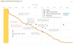
The MEM developed for the planned Well X-3 was calibrated using Well X-1 data, both wells were drilled in the same σmin direction. A MEM was used in real-time while drilling Well X-3. A minimum safe MW of 91 lb/cu ft (pcf) was recommended to drill the planned Well X-3 to minimize drilling problems due to wellbore instability. The well was successfully drilled with a MW of 92-93 pcf (Fig. 11).
The drilling of the well was continually followed on a daily basis. The nonproductive time (NPT) experienced while drilling this well based on the recommendations from the study was significantly less than its offset Well X-1. Subsequent to the drilling, the multistage fracturing assembly was successfully deployed down to TD as per design.
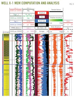
The problems encountered and lost time is shown in Fig. 11. Well X-1 has been a difficult well as a very small safe MW window was predicted. The well shows numerous breakout points in the reservoir section. The caliper log (last track, Fig. 9) illustrates a large impact in the wellbore diameter and shows significantly large bore size compared to bit size of 8½ in.
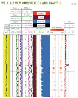
The MEM developed for Well X-3 was calibrated using observed borehole condition and drilling experience. The results are displayed in Fig. 10 where formation unit, lithology, reservoir pressure, the stress parameters (σmin, σmax, and σv) are displayed.
Also depicted in Fig. 10 are the geomechanical properties such as UCS, tensile strength, Poisson's ratio (v), and friction angle. These properties are used to calculate the most important drilling parameters the MW window including kick (brown), shear failure or breakout (red curve), losses (blue curve), breakdown (black curve) MWs, and lowest MW experienced by wellbore during drilling (MW_Nom_LB) represented by the green line in track 4.
Fig. 10 also includes the synthetic image of breakout and tensile induced fracture as well as the caliper log and bit size. As is obvious from Fig. 10, very little difficulty was encountered and the last two tracks show insignificant breakouts and the borehole size matches the bit size.
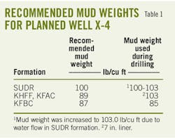
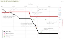
Following the same work flow, the recommended MW for Well X-4 is given in Table 1. As shown in Fig. 12, the well was drilled with 100 pcf in the Sudair formation, but the MW had to be increased to 103 pcf to suppress water flow. The intermediate casing was set without any problem. The reservoir section was drilled successfully in the Khuff formation with a MW of 85 pcf.
A comparison of Figs. 11 and 12 with Fig. 1 shows the decrease in drilling events, thereby reducing the NPT. This decrease in drilling events can be attributed to the effort invested in planning, constructing, and calibrating the MEM and using the recommended MWs while drilling.
These examples have successfully demonstrated the value and importance of using the MEM work flow to optimize MW and to decrease NPT and have brought great success to drilling operations.
Completion and fracturing
The benefit of continuous evaluation and analyses of drilling activity, simultaneously calibrating MEM, and making real time prediction is to minimize drilling time, reduce wellbore stability related problems, and drill an even borehole such that the completion system is smoothly deployed.
The openhole completion is placed such that the fracturing ports align with the best developed intervals, and the packer systems are placed against strong, tighter rocks for completion stability against impacts caused during pumping.
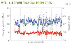
Fig. 13 presents Young's modulus and Poisson's ratio computed by MEM from openhole logs. The figure also illustrates the fracture port placements.
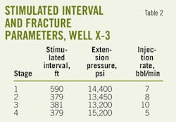
The interval covered by each fracture stage is provided in Table 2 where the fracture extension pressure and the breakdown rates are also provided.
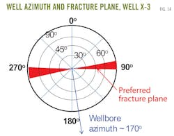
Fig. 14 illustrates the preferred fracture plane and the wellbore azimuth for Well X-3.
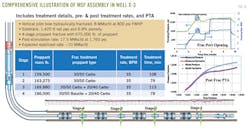
Fig. 15 is a comprehensive illustration showing the open hole completion assembly customized for Well X-3 which was drilled along σmin to maximize the number of fracture treatments. Four fracture stages were designed based on the reservoir development, thereby having four ports and several isolation packers in between.
Well X-3 was subsequently fractured successfully with more than 650,000 lb of total proppant mass in four stages. The well was partially cleaned up and tested at a rate of 17.5 MMscfd at 1,760 psi of flowing wellhead pressure (FWHP). An expected stabilized flow rate for this well is 10 MMscfd.
Fig. 15 also illustrates the successful opening of fracture ports with hydraulic pressure before initiating the first stage fracture treatment. The fracture port opening is indicated by the pressure drop during the injection period as indicated by the circles.
Production forecast
All the wells completed with MSF have been tested after fracture treatments and some have been put to production.
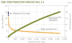
Production from Well X-4 as given in Fig. 16 shows the initial match of the production rate and subsequent 10 years forecast. The model assumes 640-acre spacing and uniform reservoir development.
The parameters used to compute long-term production have been calculated from the pressure transient tests performed on this well after multistage fracture treatment. Data from this well and other wells testify the benefits of generating independent multiple hydraulic fractures to optimally drain the reservoir. The possibility of generating such fractures is high when a well is successfully drilled in the direction of σmin.
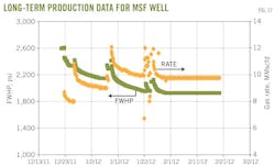
Fig. 17 presents another well where three-stage treatment was performed. The production data for 3 months show sustained rate of 8.5 MMscfd at 2,200 psi FWHP. The examples illustrate the successful nature of MSF treatments.
Results of the work
The following conclusions are deduced from MEM technology application in Saudi Aramco gas fields.
• Optimum well placement (well trajectory and azimuth) is essential for the successful application of MSF technology. Wells placed in the direction of σmin provide the best chance of placing multiple hydraulic fractures without causing overlaps.
• The wellbore integrity and stability is a legitimate concern while drilling a well in the σmin direction. This is because stresses on the openhole section are increased, and breakouts and breakdowns can happen more frequently. Prediction and use of correct MWs are essential to maintain wellbore stability and create a smooth and even section in the reservoir interval. Subsequent deployment of MSF assembly thereby becomes easier and more efficient.
• MEM is an essential tool to be developed and used while drilling. The model should be used to properly design MW window and relevant geomechanical properties using offset well data and then continuously be updated and used for prediction during the actual drilling of the well.
• Real time usage of MEMs has proved to be successful in predicting accurate MW information; wells have been drilled with minimum borehole-related problems.
• Drilling horizontal wells in the direction of σmin and completing and stimulating them with MSF have provided great success, and optimal production rates have been achieved. This strategy is currently being used in Saudi Aramco in its moderate and tight gas reservoirs.
References
1. "2009-2011 Gas Program," Saudi Aramco Gas Reservoir Management Division internal documentation.
2. Rahim, Z., Al-Anazi, H., Malki, B., and Kanaan, A., "Optimized stimulation strategies enhance Aramco gas production," OGJ, Oct. 4, 2010, p. 66.
3. Rahim, Z., Al-Kanaan, Adnan, Al-Anazi, Hamoud, et al., "Openhole multistage fracturing boosts Saudi Arabia gas well rates," OGJ, June 6, 2011, p. 66.
4. Al-Qahtani, M.Y., and Rahim, Z., "A mathematical algorithm for modeling geomechanical rock properties of the carbonate and pre-Khuff reservoirs in Ghawar field," SPE 68194, presented at the SPE Middle East Oil Show, Bahrain, 2001.
5. Rahim, Z., Al-Qahtani, M.Y., Bartko, K.M., et al., "The role of geomechanical earth modeling in the unconsolidated pre-Khuff field completion design for Saudi Arabian gas wells," SPE 84258, presented at the SPE Annual Technical Conference and Exhibition, Denver, Oct. 5-8, 2003.
6. Rahim, Z., Al-Qahtani, M.Y., and Buhidma, I., "Improved gas recovery from acid of hydraulic fracturing," Saudi Aramco Journal of Technology, Spring 2001, pp. 50-60.
7. Plumb, R.A., "Influence of composition and texture on failure properties of clastic rocks," SPE/ISRM 28022, Eurock, August 1994.
8. Plumb, R.A., Edwards, S., Pidcock, G., Lee, D., and Stacey, B., "The mechanical earth model concept and its application to high risk well construction projects," IADC/SPE 59128, presented at 2000 IADC/SPE Drilling Conference, Louisiana, Feb. 23-25, 2000.
The authors
Zillur Rahim ([email protected]) is a petroleum engineering consultant with Saudi Aramco's gas reservoir management department. His expertise includes well-stimulation design and optimization, pressure transient test analysis, gas field development, planning, and reservoir management. Before joining Saudi Aramco, he worked for Holditch & Associates Inc. and Schlumberger Reservoir Technologies in College Station, Tex. He has a BS in petroleum engineering from Institut Algerien du Petrole and an MS and PhD in petroleum engineering from Texas A&M University.
With more than 15 years of diversified experience in the oil and gas industry, Adnan A. Al-Kanaan ([email protected]) is manager of gas reservoir management department in Saudi Aramco where he oversees three gas reservoir management divisions. Reporting to the chief petroleum engineer, he is responsible for taking strategic decisions to enhance, sustain, and deliver gas to meet domestic energy demand. He oversees operating and business plans, new technologies and initiatives, unconventional gas development program, and overall work, planning, program, and decisions made by his more than 70 department engineers and technologists. He is a key player in promoting and guiding Saudi Arabia's shale and tight gas development programs. He has a bachelor's in chemical engineering from King Fahad University of Petroleum & Minerals.
Hamoud A. Al-Anazi ([email protected]) is general supervisor of the north Ghawar gas reservoir management division for Saudi Aramco. He oversees all work related to the development and management of huge gas fields like Shedgum, Uthmaniyah, and Ain-Dar. He also heads the technical group responsible for all stimulation treatments conducted in nonassociated gas reservoirs. His areas of interest include formation damage, fluid flow in porous media, and gas-condensate reservoirs. He has a BS in chemical engineering from King Fahad University of Petroleum & Minerals and an MS and a PhD in petroleum engineering from the University of Texas-Austin.
Mahbub S. Ahmed ([email protected]) is a petroleum engineering consultant with south Ghawar gas reservoir management division. His expertise includes reservoir management, gas field development, and reservoir simulation. He previously worked as a senior reservoir engineer with Occidental Oil & Gas Co. in Bakersfield, Calif., Geoquest and Scientific Software-Intercomp in Denver, and Algeria's state Sonatrach. He as a BS from Institut Algerian du Petrole and an MS from the University of Oklahoma, both in petroleum engineering.
