Arctic offshore oil pipeline will move production before yearend
In early 2000, BP Exploration (Alaska) Inc. successfully enlarged Seal Island, a man-made gravel island offshore Alaskan Beaufort Sea, and installed the Northstar pipeline system, the first trenched subsea oil pipeline in the Arctic.
Development drilling began in December 2000 with planned production to start in fourth quarter 2001 when crude oil will be transported to the Trans-Alaskan Pipeline System (TAPS) Pump Station No. 1 via the 10-in. OD offshore pipeline and an elevated overland pipeline section.
A second 10-in. diameter pipeline currently transports natural gas from existing Prudhoe Bay facilities to Seal Island for fuel and will be used for future reservoir management purposes.1

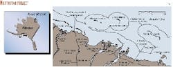
BP Exploration (Alaska) and minority leaseholder Murphy Oil Co. acquired the Northstar Unit Lease, 6 miles offshore the Alaskan Beaufort Sea coast, in 1995 (Fig. 1). Shell discovered the oil field in 1983 with exploration wells drilled from Seal Island. Amerada Hess also evaluated developing this field but abandoned the island in 1994.
Part of the historical developmental challenge associated with the Northstar field was its location in approximately 37 ft of water.
Offshore Arctic
The Northstar Project location is characterized by long, ice-covered winter seasons followed by short summer open water seasons, when the natural environment is most sensitive.2 Initial planning for the pipeline construction concluded that winter ice-based installation methods were best suited to these conditions.
This set the direction for much of the subsequent pipeline permitting, design, and construction planning efforts.
Overland pipelines on the Alaskan North Slope have, in recent years, been constructed during the winter from temporary ice roads made by spreading water on the tundra to protect the fragile vegetation.
The 11-mile overland section of the Northstar oil pipeline is supported 5 ft aboveground on conventional vertical support members to protect the tundra from melting and allow caribou passage.
The light (42° API gravity) Northstar oil is first cooled on Seal Island to an average annual temperature of 50° F. before being pumped through the uninsulated subsea pipeline.
The overland pipe has 2-in. thick polyurethane foam insulation with a galvanized metal jacket to minimize further heat loss in winter air temperatures that reach -50° F.
Environmental loading
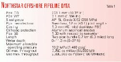
The Northstar pipelines satisfy conventional offshore-overland pipeline design requirements (Table 1).
The offshore pipeline wall thickness was selected to provide a high pipe specific gravity (1.60 with respect to seawater) for stability during trench backfilling operations.
A secondary effect of the low pipe diameter-to-wall thickness ratio (D/t = 18.1) is that the wall thickness is a conservative 2.8 times the design-code requirement for internal pressure containment. Cathodic protection includes a dual layer fusion bonded epoxy coating and low-temperature aluminum anodes.
The offshore arctic environment can apply several unique loading conditions on buried subsea pipelines. At the same time, however, an efficient design was needed for compatibility with the planned winter ice-based construction techniques.
An excessively deep trench, longer offshore route, or other difficult construction requirements could potentially jeopardize pipeline completion in a single winter construction season or could otherwise increase potential environmental impacts from construction activities.
A limit-state design approach was therefore used to help optimize the offshore pipeline.
Following are specific environmental loading conditions for trenched subsea pipelines in the Arctic.3
- Seabed ice gouging. Irregular ice keels under floating sea ice periodically gouge the seabed. The Northstar pipelines are in a relatively sheltered portion of the seasonal landfast winter ice zone where the deepest seabed ice gouge observed over 10 years was 2 ft.
The maximum predicted gouge depth along the pipeline route during a 100-year period was estimated at 3.5 ft.
An ice keel gouging the seabed applies stresses to the soil, which induce vertical and lateral soil displacements and affect the pipeline.4 These vary with depth below the seabed, soil type, and the gouge depth, width, and orientation.
- Seabed permafrost thaw settlement. Ice-bonded permafrost is found along the Northstar offshore pipeline route in water depths less than 5 ft. This includes the 2-mile section in the shallow Gwyder Bay lagoon where the sea freezes down to the seabed.
Because the Northstar pipelines are designed to operate at temperatures greater than the soil pore water freezing point, a thaw bulb will form around the pipes. The overburden load initially shared by the soil and frozen water will be transferred to the soil skeleton allowing thaw settlement to result.
Buried warm pipelines transitioning through thaw-sensitive permafrost will lose support and settle with the soil.5 The Northstar pipeline maximum design settlement is 2 ft.
- Strudel scour. Strudel scour craters form in the seabed during spring breakup when the river overfloods the bottomfast sea ice in the nearshore zone.6 The flood water drains through holes in the ice sheet, eroding seabed sediments.
If the scour occurs above the pipeline and is deep enough, it can form an unsupported pipe span, which is subjected to hydrodynamic and gravitational loads.
Survey data show, however, that large or deep strudel scours in the Northstar pipeline area seldom occur. Therefore, strudel scour did not govern trench depth requirements.
- Upheaval buckling. Buried pipelines, operating at elevated temperatures, can develop compressive forces and move up through the trench backfill at the crest of overbend areas.7
The bending strain compliant design of the Northstar pipelines would minimize the potential for leakage following an upheaval buckle, but the pipeline may become exposed to sea ice impacts.
The pipelines are designed to resist upheaval buckling at the maximum operating temperature of 100° F. The minimum native soil backfill thickness above a 2-ft prop or overbend was calculated to be 5 ft.
- Trenching requirements. The Northstar design included modeling pipe-soil interactions to establish the trench depth needed to ensure pipeline integrity.
The effect of soil displacement and the pipeline resultant load was modeled with non-linear finite-element analysis with plastic steel behavior and large displacement capabilities.
Displacement-controlled soil loading conditions were applied, including seabed ice gouging and permafrost thaw subsidence.3 Analysis indicated that a few feet of the Northstar pipeline may develop maximum bending strains of approximately 1.4% due to extreme event ice keel loadings.
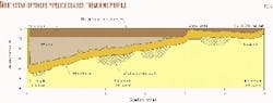
Permafrost-thaw-settlement analysis conservatively calculated maximum pipe bending strains of about 1.1%. The minimum pipeline depth of cover (original seabed to top of pipe) was determined to be 7 ft (6 ft in the lagoon area; Fig. 2).
Bending design
The Northstar offshore pipelines were designed safely to sustain bending strains several times the yield strain, in response to potentially severe arctic loads. Extreme loads may cause large displacements, inducing plastic strains, but the ultimate limit-state condition (pipeline rupture) will not be exceeded.
Steel pipelines commonly bend beyond their yield strain limits during construction. This application of limit-state bending confirms that an ultimate limit-state condition was not exceeded by as-built pipe inspection and hydrotesting.
Operational pipelines require limit-state-bending strain evaluations only after an unplanned loading event. Incorporation of limit-state-bending criteria into the original pipeline design for operational conditions is less common.
The limit-state design procedure avoids all limit-state conditions in which nonconformity would interfere with the functional aspects of the pipeline system.
Design of the Northstar pipelines used existing design codes and standards to perform a project-specific Engineering Critical Assessment (ECA) for bending limit state conditions.8
The lack of a single industry standard for this analysis, however, increased the importance of experimental validation of the limit strain criteria.
Pipelines exposed to bending in excess of conventional stress-based design limits must resist the following potential failure mechanisms:
- Localized buckling or excessive ovalization preventing the passage of inspection pigs or even leakage.
- Unstable weld-flaw propagation causing a girth weld fracture or pipeline crack and subsequent leakage.
Once the limit-state bending strain values were determined, safety factors against failure were applied for operational and extreme event loading. Larger safety factors were applied to operational loading such as permafrost thaw settlement, which will be monitored during pipeline operation.
Because extreme event loads, such as ice gouging, are less likely to occur, they warranted a lower safety factor. Smaller safety factors were also applied to the less critical limit state of buckling.
Limit state pipeline bending design can be advantageous for other noncyclic, displacement-controlled loads, including, free spans or when subject to soil movement. Factors influencing pipeline limit state performance, however, must be thoroughly assessed.
Buckling; weld limit state
Localized buckling is a limit-state condition, setting the compressive strain limitation on the inside chord of a pipe bend. It is governed by a combination of bending strain, pipe dimensions, initial ovality, and external pressure.
The Northstar pipeline's low D/t helps resist localized pipe body buckling. The most conservative of the empirical design relationships predicts a compressive bending strain limit of 2.4%.
The observed buckling strain limit during the Northstar full-scale bend tests was 5-6%. A fully developed buckle, but no leak, occurred when a pipe sample was subjected to a 10% strain.8
The weld-fracture limit state is a tensile strain limitation on the outer chord of a pipe bend. It only applies when a girth weld is in the zone of maximum tensile strain.
It was assumed that 1) the maximum allowable weld flaw was present in the weld, 2) that it coincided with the maximum allowable weld fit-up high/low, and 3) that the flaw was at the point of maximum tensile strain. This provided very conservative limit-strain criteria for the Northstar pipelines.
The critical weld-flaw size assessments procedures outlined in PD 6493 were applied to the Northstar pipeline. The analysis' input parameters included pipe dimensions and stress intensification factor, together with steel yield, ultimate tensile, residual welding, and flow stress values.
Calculations were performed to establish the critical weld-flaw length for a given value of tensile strain, design CTOD value, weld misalignment, and planer flaw depth (CTOD = crack tip opening depth). The Northstar full-scale bend tests documented the pipeline's resistance to weld tensile fracture.
The Northstar linepipe was manufactured to a specification related to the bending limit state design.
Pipeline welding; offshore construction
The welding specification was based on the limit-state design requirements, and the manual shielded metal arc welding (SMAW) technique used for conventional overland pipelines on the Alaskan North Slope.
Girth weld non-destructive examination used both X-ray radiographs and automatic ultrasonic inspection. A project-specific NDE qualification program concluded that both NDE methods could have significant inaccuracies in sizing artificial weld flaws.
The engineering critical assessment required that actual weld flaw sizes should be smaller than those predicted as critical for fracture initiation; both methods were employed, therefore.
This double-weld inspection requirement provided a conservative approach to ensure pipeline integrity, but it proved difficult to apply in the field. Any flaws that exceeded the acceptance criteria were cut out and the pipe rewelded.
Construction mobilization started in late 1999.
An important component of the construction planning and mobilization involved BP's health, safety, and environmental program. The Northstar construction permitting process included extensive discussions with local, state, and federal permitting agencies. All field personnel were given site-specific training.
Offshore site safety included the established North Slope procedures for limited visibility (phased) travel restrictions and logging on/off of all personnel at the offshore work site. There were full-time project staff assigned to safety, security, and environmental compliance monitoring.
Civil works; pipe fab
Seal Island reconstruction began in January 2000 with ice-road building, blasting and hauling of gravel from an onshore mine site, and driving open cell sheet pile walls for the island.
Offshore pipeline construction civil works by Alaska Interstate Construction also started in January with the removal of snow from the right-of-way and leveling of the sea ice. Floating sea ice was thickened to at least 8 ft along the pipeline right-of-way by the pumping of seawater onto the surface in successive 2-in. lifts and allowing it to freeze.
Site access roads were preferentially built on the smooth bottomfast ice along the shoreline and capped with fresh water. Snow removal and ice road maintenance were continuous operations during pipeline construction.
Pipeline trenching started in March 2000 in the lagoon area and was completed in April 2000 at Seal Island. The permafrost at the Point Storkersen shore-crossing site was blasted and excavated about 180 ft onshore to allow installation of a vertical transition to the aboveground pipelines.
Trenching started with cutting an 8-ft wide slot in the ice surface. The excavated ice was then trucked to a remote disposal site.
The condition and loading of the floating ice sheet were continuously monitored to ensure that the weight of equipment and excavation spoils were within the loading limits.
The ice work surface was bottomfast within the lagoon area and spoils could be safely windrowed along the trench.
Offshore trenching employed four backhoes mounted on marsh buggy undercarriages equipped with extended reach booms.
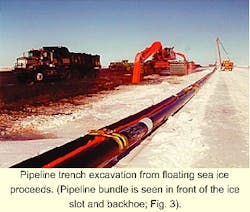
The backhoes could therefore straddled the ice slot and load directly into dump trucks (Fig. 3).
Spoils were taken to a site on bottomfast ice, spread out, and allowed to freeze. Whenever possible, spoils were returned directly into the slot to cover the pipeline.
The slot was cleared of any refrozen ice, and the trench was cleaned and surveyed immediately before pipelay. Afterwards, the remaining frozen trench spoils were reclaimed and backfilled into the trench through the ice slot.
Condition and loading of the floating ice sheet were continuously monitored to ensure that the weight of equipment and excavation spoils were within the loading limits. The ice work surface was bottomfast within the lagoon area and spoils could be safely windrowed along the trench.
The two 10-in. pipelines were fabricated by Houston Contracting Co. along the opposite side of the trench from the civil work.
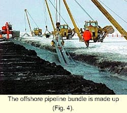
Pipe joints were strung out, welded, inspected, and field joints were coated in a similar manner to that used for conventional overland pipelines (Fig. 4).
The process was repeated for the second line. Pipe fabrication was performed on a single shift basis, starting Feb. 23, 2001, and took approximately 5 weeks. The pipelines were bundled together with the LEOS leak-detection tube, which was installed in a 2-in. diameter protective plastic pipe.
The bundle was then lowered to the trench bottom with four sidebooms equipped with roller cradles. Roller elevations and sideboom spacing were controlled to limit installation stresses as the pipe was lowered to a 50-ft total water depth without applying axial tension.
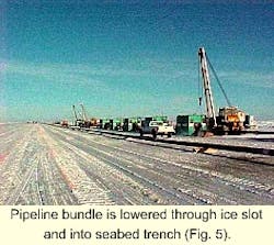
Pipeline lowering was completed at the same time as the pretrenching. The trench terminated at a vertically curved sheet pile slot in Seal Island (Fig. 5). The pipelines were hydrostatically tested with a water-glycol mix and inspection pigs were run prior to demobilization.
The ice road to Seal Island remained in service for truck transport through late May.
Operational requirements
During the permitting process, the Northstar project permitting process focused attention on the sensitive Alaskan Beaufort Sea environment and the potential hazard posed by pipeline leaks.
The Northstar pipeline thick-wall design and lack of subsea pipe fittings will minimize the potential for very small leaks that are difficult to address with conventional pipeline leak-detection technology.
Additionally, the pipeline operating plan includes an aggressive combination of pipeline route surveillance, inspection pigging, and leak-detection systems.
Pipeline inspection will routinely use a pig that will include a combination of pipe-wall thickness measurement and 3D geometry pig surveys. These inspections will identify potentially excessive pipe corrosion and permafrost thaw settlement-induced bending strains. Any necessary pipeline repairs would then be performed before a pipe failure could occur.
Northstar's conventional pipeline leak detection system includes pipe monitoring with both pressure point analysis and mass balance line pack compensation systems.
These systems will be supported by a leak-detection system designed to sense the presence of hydrocarbons outside the pipelines.
The LEOS system selected for this first offshore pipeline application depends on hydrocarbon diffusion into a buried sensor tube. Air in the tube is periodically displaced and passed through a sensitive gas detector to identify the presence of a potential hydrocarbon leak.
The LEOS tube was installed as part of the offshore pipeline bundle.
The success of the Northstar development project results from a combined effort of BP and the Northstar alliance: Alaska Interstate Construction, Alaska Petroleum Contractors, Coastal Frontiers Corp., Houston Contracting Co., INTEC Engineering Inc., Mustang Engineering Inc., National Tank Co., Sandwell Inc., VECO Alaska Inc., and VECO Engineering Inc.
Acknowledgment
The author thanks BP Exploration (Alaska) Inc. for permission to publish this article.
References
- Lanan, G.A., Ennis, J.O., Egger, P.S., and Yockey, K.E., "Northstar Offshore Arctic Pipeline Design and Construction," Offshore Technology Conference, Apr. 30-May 3, 2001, Houston.
- US Army Corps. of Engineers, Final Environmental Impact Statement: Beaufort Sea Oil and Gas Development/Northstar Project, Alaska District, Anchorage, 1999.
- Lanan, G.A., Nogueira, A.C., McShane, B.M., and Ennis, J.O. "Northstar Development Project Pipelines Description and Environmental Loadings," International Pipeline Conference, Oct. 1-5, 2000, Calgary.
- Nixon, J.F., Palmer, A., and Phillips, R. "Simulations for Buried Pipeline Deformations Beneath Ice Scour," Proceedings of 1996 ASME Offshore Mechanics and Arctic Engineering Conference, Vol. 5, pp. 383-92.
- Nixon, J.F., "Thaw-subsidence Effects on Offshore Pipelines," ASCE Journal of Cold Regions Engineering, Vol. 5 (1991), pp. 28-39.
- Leidersdorf, C.B., Gadd, P.E., and Vaudrey, K.D., "Design Considerations for Coastal Projects in Cold Regions," 1996 ASCE International Conference, Coastal Engineering Research Council.
- Palmer, A.C., Ellinas, C.P., Richards, D.M., and Guijt, J. 1990, "Design of Submarine Pipelines Against Upheaval Buckling," 1990 Offshore Technology Conference, Houston.
- Nogueira, A.C., Lanan, G.A., Even, T.M., Fowler, J.R., and Hormberg, B.A., "Northstar Development Pipelines Limit State Design and Experimental Verification," International Pipeline Conference, Oct. 1-5, 2000, Calgary.
The author

Glenn A. Lanan is a senior project manager with INTEC Engineering Inc., Houston. He has more than 24 years' experience in the design and construction of offshore pipelines. Lanan holds a BCE and Master of civil engineering from the University of Delaware and is a registered professional engineer in Alaska and Texas.