Acid washes, oxygenate scavengers work against gas gathering failures
Hamed Mansoori Reza Mirzaee
National Iranian Oil Co.
Abdul Hassan Mohammadi
South Zagros Oil & Gas Production Co.
Feridun Esmaeilzadeh
Shiraz University
Shiraz, Iran
| Based on presentation to International Petroleum Technology Conference, Beijing, Mar. 26-28, 2013. |
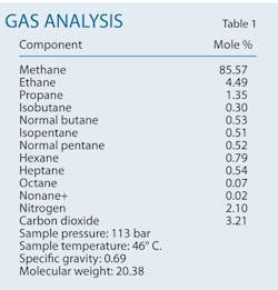
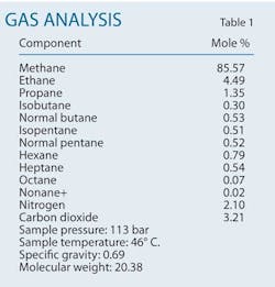
A combination of acid washes and oxygenate scavengers can both reduce the frequency of pipeline failures caused by existing pitting corrosion and prevent new pitting corrosion. This article applies such an approach to natural gas transmission pipelines subject to frequent failures in a gas production field in southern Iran. The gas condensate field has more than 30 wells, with total natural gas production around 46-million standard cu m/day. Produced condensate totals about 10 bbl/MMscfd of gas production. Table 1 shows the field's gas analysis.
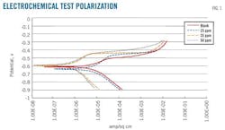
The wells have varying amounts of carbon dioxide, but all are considered sweet gas. Amine-based corrosion inhibitors (CI) prevent or mitigate internal corrosion. Laboratory electrochemical polarization tests, as well as field data from corrosion monitoring coupons and monitoring of iron ion counting, determined optimum CI concentration and injection rate. Diluting the CI in gasoline and stabilized gas condensates increases its fluidal and adherence factors.
A high concentration of chlorine and CO2 in wet gas provides a powerful electrolyte for CO2 corrosion, or so-called sweet corrosion.1 2 Many theories address the corrosion mechanism of steel in an aqueous, CO2-saturated environment.3
Electrochemical tests
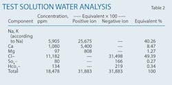
Material specimens for electrochemical tests were prepared from damaged API 5L X65 carbon-steel pipes. Specimens have a cross section of 1 sq cm in flush shape. A wet grind with 240-grit SiC paper, followed by a wet polish with 800-grit SiC paper until previous coarse scratches are removed, a rinse, and a dry prepares the specimens for testing.4 Degreasing and a rinse in distilled water immediately preceded immersion. The test electrolyte was a 250 ml solution of water produced from one of the gas condensate wells (Table 2).
Electrochemical tests occurred in a glass cell using working, reference, and auxiliary electrodes. Reference and auxiliary electrode were Ag/AgCl and platinum, respectively. An oxygen-free gas such as nitrogen bubbled into the solution for about 1 hr to reduce its oxygen levels prior to immersing the material specimens. During the polarization tests, continuous ventilating of CO2 into the solution kept it saturated.
A pH meter with accuracy of ±0.01 calibrated by 4-7 buffer solutions measured pH. Film-forming imidazoline derivations were the applied inhibitor. Testing measured open-circuit potential (OCP) until it stabilized, yielding the corrosion potential. After 50-min immersion, OCP potentiodynamic tests occurred in a Tofel range of ±300 mv with a potential scan rate of 1 mv/sec and at a temperature of 60° C. (Table 3).
The electrochemical tests demonstrated a need for 50-80 ppm of continuous CI injection at the wellhead facilities (Table 4).
Corrosion monitoring
Corrosion monitoring coupons were discs and strips using C1018 material. Wellhead facilities used the discs, with strips used in gas gathering units. The absence of much free water right after exit from the wellhead christmas tree and the higher fluid velocity than seen downstream at gas gathering units forced use of disc type coupons installed at the ceiling of the pipe. Coupons monitored batch injection of CI and corrosion condition of tubing inside the well column.
The operational conditions of gas gathering units allowed the precipitation of more liquid out of the flowing fluid than wellhead conditions. This environment lends itself to use of strip-type coupons for internal corrosion monitoring of the pipes, their contact with the aqueous phase being more effective.
All coupons were in service for 6 months and then retrieved to measure the lost weight. Table 5 shows the coupon results.
The data from electrical resistance (ER) probes installed with the coupons at both wellhead and gathering sites differed from the weight-loss coupon measurements in some cases. Table 5 data show a controlled uniform corrosion rate for the pipelines except for at some wellhead facilities, where the coupons demonstrated considerable corrosion.
All wellhead surface pipes measured 6-in. OD and the buried flowlines, from wellheads to manifolds, 10-in. ID. Wells with higher flow rates showed evidence of erosion-corrosion at wellhead facilities. Such wells require consideration of the fluid's erosional velocity, with internal corrosion direct assessments confirming erosion-corrosion at such sites.
Atomic absorption, photometry, and volume titration can measure iron counts in the aqueous phase. Atomic absorption can determine dissolved iron and ferrous iron or total iron in the aqueous solution. Direct atomizing of aqueous samples determines dissolved iron, which is then reported in ppm. Total iron counts determination is similar to soluble iron but in the presence of HCl or nitric acid. The photometric method can present ferrous and ferric iron separately.5
This article used atomic absorption for iron counting. Judging the corrosion rate requires considering the amount of water the wells produce, with in turn allows conversion of the iron count to an iron production rate, usually expressed in kg/day: Iron production rate, kg/day = iron count, ppm × produced water, l./day.
The similarity in operational conditions, materials, and chemical treatments for the facilities studied make it possible to evaluate and compare iron counting. Wells containing dissolved sulfide cannot be evaluated in this manner due to precipitation of iron sulfide in the system. High iron counts in systems with low produced water do not necessarily indicate severe corrosion rates, just as low iron counts with high produced water did not necessarily indicate low corrosion rates.
Ions like manganese (Mn) exist in aqueous phase beside iron (Fe) when corrosion processes are present. Considering Mn ions allows determination of Fe levels in steel.5 The Mn concentration over Fe in the steels used for pipes in this article equals about 1%. If the iron count over Mn exceeds 1%, this surplus is due to existence of iron in the water formation and its source is not corrosion. There is no meaningful relationship between Mn count and pitting corrosion.
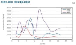
Fig. 2 compares iron ions between three wells. These data could help to optimize the actual corrosion rate parallel with other monitoring tools. The trends in Fig. 2 demonstrate the relative effectiveness of the corrosion control programs. A sudden increase in iron rates may, in some cases, be caused by something other than an increasing corrosion rate. Other main reasons for sudden increases in iron include:
• Change in corrosion inhibitor type.
• Change in operational conditions (flow rate, temperature, etc.).
• Accumulated water moving downstream.
• Sampling after cleaning pig operations.
Erosion, corrosion
Corrosion monitoring coupons on electrical resistance probes can show a high loss of metals in high-flow-rate wellheads. Internal corrosion direct assessments confirm erosion-corrosion phenomena, especially in swept bends and flanges near the wellhead's christmas tree (Fig. 3). An inappropriate sizing of the pipeline led to erosion via impingement.
Scale, pitting
Internal corrosion direct assessments revealed scales on the inner pipe wall of wells with low flow rates (< 0.6 MMscmd). The three possible reasons for such deposits in the current case include:
• Free water from hydrostatic tests left inside the pipelines before operation.
• A high fouling factor for water produced from the wells.
• Increasing pH by injection of amine-based inhibitor into the pipes causing dissolved bicarbonate to change into precipitated carbonate.
These deposits exist in all wells of the studied field. The volumetric velocity of entrained fluids in high-offtake gas wells removes the deposits and prevents them from adhering tightly to the inner surface of the pipes. Wells with low flow rate leave a high chance that these deposits adhere tightly to the pipe wall. Corrosion inhibitors will not affect corrosion processes occurring under these deposits. CI will only mitigate uniform corrosion if it can reach the pipe wall and then act as a film-forming mechanism. Pitting corrosion under deposits caused the failures studied in this article.
A 10-in. OD gas flow line could act as a mini-separator and lead to a stratified flow regime on wells with a low hydrocarbon flow rate and high salinity. Gas and liquid phases move separately in these circumstances, with gas travelling above the liquid phase and leaving the corrosive components of the aqueous phase in close contact with the pipe's inner surface. Scale deposits blended with the dissolved oxygen of a corrosion inhibitor continuously injected into the pipe lead to merging concentrative electrochemical cells under the deposits and finally cause pitting corrosion failures in a sweet-gas environment such as that studied here (Fig. 4).
Injection of only 0.1 ppm oxygen along with high-saline produced water can sharply increase corrosion rates.6 High salinity of produced brine creates a strong electrolyte conductivity. Pits grow rapidly and lead to pipe failures in these environments. All the pipeline failures in this article occurred in almost the same position, between three and nine o'clock on the pipeline. Deposits analyzed with the X-ray diffraction (XRD) method consisted mostly of wustite, hematite, mangnetite, FeCo3, and CaCo3. Mn compounds in the scales exceeded the 1.4%-Mn structure of the steel.
Intelligent pigging
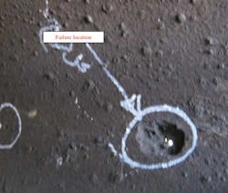
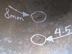
Intelligent pigging surveys investigated the internal conditions of the failed pipes. Table 6 shows results of a magnetic flux leakage pigging for one of the 10-in. OD flowlines, with many defects resulting from wall thinning detected. Such defects on the inner pipe wall may lead to near-term pitting corrosion failures (Fig. 5). The line inspected by MFL pig had experienced many pitting failures in its 2 years of operation.
Data from MFL pigging revealed ongoing problems with the pipeline, with prompt action required. Nn acid washing (foam cleaning) program removed existing deposits and oxygen scavengers alleviated the amount of oxygen introduced by corrosion inhibitors. These measures would only reduce the frequency of failures from old pits, not stop it completely, but they would also prevent new pitting corrosion.
Foam cleaning uses a static foam generator that employs air or nitrogen to produce a foamed solvent. Foam stabilizers prolong foam life and increase the effectiveness of the cleaning chemicals. Foam cleaning is used on the equipment that cannot support full or partial filling with liquid. It results in significantly less liquid volume for disposal compared with other methods.
The applied acid could be hydrochloric with a 5 to 1 wt % and mixed with an appropriate corrosion inhibitor. HCl can dissolve deposits from carbonates, phosphates, and iron's oxides. Caustic washing to degrease the metal must precede acid washing.
Acid washing removes the protective film of corrosion inhibitor. Two common methods for reintroducing this film to the pipe wall are filling the space between two sealing pigs with CI and then launching the pigs inside the pipe, and increasing the injection rate of CI to three-times normal for 72 hr.
Either injecting a blanket gas into the CI storage tanks or using an oxygen scavenger to react with dissolved oxygen and remove it from the system will prevent its entrance into the pipelines.
Acknowledgement
The authors offer special thanks to the research and development sector of Central Iranian Oil Fields Co. for their valuable support.
References
1. Newton, L.E., and Hausler R.H., (Eds.), CO2 Corrosion in Oil and Gas Production, Houston: NACE International, 1984.
2. Fontana, M.G., and Greene, N.D., Corrosion Engineering, Second Ed., New York: McGraw-Hill, 1978, pp. 51-54.
3. Sridhar, H., Dunn, D.S., Anderko, A.M., Lencka, M.M., and Schutt, H.U., "Effects of Water and Gas Compositions on Internal Corrosion of Gas Pipelines: Modeling and Experimental Studies," Corrosion, Vol. 57, No. 3, March 2001, p. 202
4. ASTM G1-90 "Standard Practice for Preparing, Cleaning, and Evaluating Corrosion Test Specimens," 1994.
5. NACE RP0192-98 "Standard Recommended Practice -Monitoring Corrosion in Oil and Gas Production with Iron Counts," 2006.
6. Baboian, R., (Ed.), NACE Corrosion Engineer's Reference Book, Third Ed., Houston: NACE International, 2002.
The authors
Hamed Mansoori ([email protected]) is a process engineer with National Iranian Oil Co. He holds a BSc in chemical engineering from Islamic Azad University, Tehran, and an MSc in chemical process engineering from Shiraz University, Iran.
Reza Mirzaee (r_mirzaeepnu.yahoo.com) is a senior corrosion engineer with National Iranian Oil Co. He received his MS in chemical engineering from Isfehan University of Technology and holds a BS in chemical engineering from Tehran University.
A. Hassan Mohammadi ([email protected]) is the operation manager of South Zagros Oil & Gas Production Co. He holds a BSc in chemical engineering from Shiraz University and an MSc in chemical engineering from Tehran University.
Feridun Esmaeilzadeh ([email protected]) is associate professor at Shiraz University, joining in 2002, and adjunct professor at the Sharif University of Technology since 2001. He served as visiting professor at Georgia Institute of Technology, Atlanta, 2010-11, and the Petroleum University of Technology and Isfahan University of Technology, 1994-2002. He has more than 10 years' experience at the National Iranian Oil Co. as an administrator of reservoir simulation, production engineering, and petrophysics. Esmaeilzadeh holds a BS (1986) from the Abadan Institute of Technology, Abadan, Iran, an MS (1990) from Shiraz University, and a PhD (2001) from Sharif University of Technology, Tehran, all in chemical engineering. He is a member of the Society of Petroleum Engineers and the Iranian Association of Chemical Engineering.
