Quick-kill workover proves effective in Libya
A quick-kill method improved workover operations in Messla field in Libya.
Since mid-2003, Arabian Gulf Oil Co. (AGOCO) has used this method for killing wells during more than 60 workovers. The method has reduced the time and costs required for working over wells, and in addition the wells resumed production in less time after the workover.
For the natural flowing wells in the field, a few swab runs restored production after the workover, while wells with electric submersible pumps (ESPs) cleaned up smoothly.
To date, the method has not caused any accident or operational problems.
Conventional workovers
The reservoirs in the AGOCO-operated Sarir Main, North, and L fields, and Messla field do not sustain more than a 7.0-ppg hydrostatic head of fluid. These oil reservoirs are at an 8,500-8,800 ft depth and have reservoir pressures of 2,500-3,000 psi.
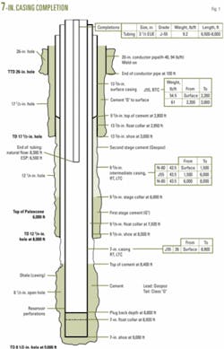
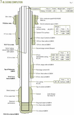
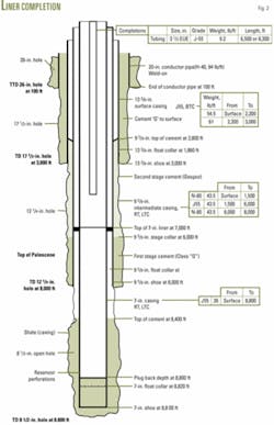
Figs. 1 and 2 show typical downhole well configurations in the fields. The well in Fig. 1 has 7-in. production casing, while that in Fig. 2 has a 7-in. production liner.
The wells produce with either natural flow through 31⁄2-in. open-ended tubing, with some wells having a 7-in. packer at 8,300 ft, or with artificial lift provided by an ESP placed at about 6,500 ft.
Conventional workovers typically killed these wells using reverse circulation with about 500 bbl of 8.4-ppg brine, containing an impure salt (NaCl2). The procedure involved continuing to circulate the fluid until some oil and gas (burnt at the flare pit) and partial brine were recovered at the surface. In some wells, a U-tube effect up the 31⁄2-in. production tubing or a vacuum effect prevented any substantial brine returns.
Some shortcomings of these conventional killing procedures include:
• Kill fluid invasion into the reservoir that causes permanent or temporary formation damage that requires additional treatments after completing the workover.
• Inability of the weighting material, such as impure NaCl2, to prevent damage from clays swelling in the sandstone reservoirs. The weighting material also contributes to fluid invasion.
• Extensive swabbing (2-7 days) to bring wells back on production after the workovers. Wells with ESPs also often required swabbing.
• Decline in well productivity, as noted in post-workovers production, at least during the initial production following workovers.
• Extensive consumption of consumables, such as swab cups, saver rubber, sand line, fuel and lubricants, kill water, and salt.
• Lengthy workovers caused by the extended swabbing time for bringing wells back on production.
• Lost time waiting for water supplies. Trucks haul water from source wells to the rig site where it is transferred to rig tanks. This operation can take days and is a function of well location, number of operating rigs, and number of trucks available to haul water. This can increase the workover operating costs because contractually the workover rig costs start once the rig is 100% rigged up on location.
AGOCO management realized these concerns and began a program to find a practical kill method that would eliminate or mitigate the previously listed shortcomings.
New method
The reservoir cannot sustain a hydrostatic head of a column of fluid with a gradient higher than 0.33 psi/ft. The shut-in well, therefore, can be killed by an augmentation of the existing shut-in hydrostatic head, taking into account shut-in wellhead pressures. This involves squeezing 8.35-ppg water into the annulus.
To facilitate extraction of the production string, water needs also to displace the tubing capacity. Squeezing water into the tubing displaces the shut-in contents, which usually is a small oil and gas volume.
Based on standard well-killing procedures and upon reviewing the conditions of producing and shut-in wells in AGOCO fields, the following data and observations were used to determine a new and practical well-killing procedure:
• A dynamic level of fluid (DFL) in the annulus exists while the well is on production. This level is monitored on a regular and on a well-by-well basis.
• A shut-in well has a static fluid level (SFL) in the annulus, where associated gas accumulates during productions and shut-in periods. Sonolog techniques can determine the SFL depth.
• The shut-in pressures (tubing and annulus) are recorded before killing operations.
• The current reservoir pressures (PR) are available from well production history and are continuously updated.
• The production tubing and production-casing annulus, under shut-in conditions, contains gas, oil, and reservoir water in various proportions down to the reservoir.
• The annulus, down to the SFL must be filled with kill fluid during killing operations to minimize gravitational segregation after the well is killed.
• A field specific safety/trip margin (SM) that can have a positive, negative, or null valve and allows for SFL depth, keeping the fluid off the reservoir, and pulling the tubing (possible swabbing) after the well is killed.
• The casing shut-in pressure (SICP) determines the minimum volume of the water required to bring the well under control.
• Discontinue the use of weighting materials (commercial salt). The water source well provides 8.35-ppg water.
• The kill fluid should not go below 6,500 ft. This would leave the wellbore across the reservoir filled with reservoir native fluids, hence, preventing reservoir invasion and damage.
Pressure balance equations
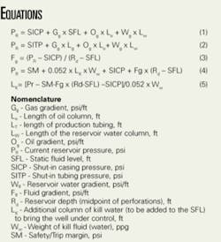
Equations 1 and 2 (see equation box) are the pressure-balance equations under shut-in conditions. Equation 1 is for the 31⁄2-in. production tubing and production casing annulus, while Equation 2 is for the production tubing.
Some fluid properties and length of columns in addition to transition zones from one phase to another are difficult to define; therefore, the calculation assumes wellbore fluids would have two composite but distinct phases: liquid from the producing interval to the SFL with a gradient of Fg and gas from the static fluid level to surface with a gradient of Gg.
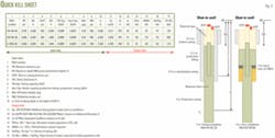
In addition, most of the kill fluid is pumped down the production tubing and production-casing annulus; accordingly, the assumption is applied to the annulus (Fig. 3). Moreover, the tubing must eventually be displaced to water during killing operations.
The calculations assume the gas gradient (Gg) is negligible; nevertheless, the SICP is transmitted through the gas phase to the top of the liquid phase at SFL. Equation 3, therefore, can estimate the fluid gradient under shut-in conditions.
Equation 4 is the pressure-balance equation to bring a shut-in well under control through quick-kill operations, and Equation 5 calculates the additional column of kill water (to be added to the SFL) to bring the well under control.
Quick-kill procedure
A pilot test in the Messla field used the following procedure to kill a well:
• Create an Excel program (Fig. 3) to aid the field staff in doing the calculations.
• Record the shut-in pressures from the wellhead.
• Obtain SFL, Lt , and current PR from well-production history.
• Insert the input data in the quick-kill sheet.
• Read the output data for the total annular volume of water necessary to control the well (ANNv) and water to be pumped down the tubing (Vwtgb). Note that the tubing has to be completely filled with the kill water before extraction; therefore, its entire volume has to be added to the volume of water required.
• Prepare to kill the well.
• Bleed off casing pressure.
• Squeeze the ANNv down the annulus, keep the tubing shut in.
• Shut in annulus and bled off tubing pressure.
• Squeeze the (Vwtbg) down the tubing.
• Monitor SITP and SICP. These must be zero or on vacuum.
• Open the tubing and the casing then observe the well for 30 min.
• Nipple down x-mas tree and nipple up blowout preventers.
• Proceed with workover program.✦
The author
Wathik M. Alhashimi is a senior engineering specialist-drilling, completions and workovers for the Arabian Gulf Oil Co., Benghazi, Libya. He resides in Calgary. Previously he worked in management and engineering for several other petroleum and oil field service and supply companies in Canada, South America, and the Middle East. Alhashimi has an MS in petroleum engineering from the Petroleum, Gas, and Geology Institute, Bucharest. He is a member of the Association of Professional Engineers, Geologists, and Geophysicists of Alberta.
