DRILLING BRAZILIAN SALT-1: Petrobras studies salt creep and well closure
Petrobras’s numerical simulations by finite-element modeling yielded a preliminary two-stage drilling strategy through thick salt sections in the Santos basin off Brazil.
The presence of evaporite sections in prospects for oil or gas exploration increases the probabilities of success due to conditions that favor the generation and trapping of hydrocarbons. But many operational problems, such as stuck pipe and casing collapse, have been reported by the industry when drilling through salt layers.
Historically, in the Campos basin off Brazil, several deep wells have been drilled through thick salt intervals. Up to the 1990s, the lack of reliable methods to predict salt behavior at high temperatures and high differential stresses led to very high drilling costs and even loss of wells.1
This two-part series of articles presents experimental results, and numerical simulations, by finite-element analysis used to develop a method of designing drilling fluids and casing and a strategy to drill at great depths through thick salt layers.
Petrobras ran numerical simulations to evaluate the creep behavior of salt rocks (halite, carnallite, and tachyhydrite) at high differential stress and high temperature, using finite-element code developed in-house.
The numerical simulations were run on a prospect in the Santos basin with a 2,000-m thick section of different evaporite rocks with high creep rate. The results were used to predict the evolution of the well closure over time for various drilling fluids, and scientists analyzed several alternatives for a drilling strategy.
The casing design, presented in the concluding part, was accomplished with several failure scenarios that involved cementing the casing and borehole annulus through the salt and retaining drilling fluid in the annulus to determine the nonuniform loading and timing of salt loading on well casing deformation or ovalization. The casing was designed to support the high creep rates of carnallite (KC·MgCl2·6H2O) and tachyhydrite (CaCl2·2MgCl2·12H2O).
Santos basin
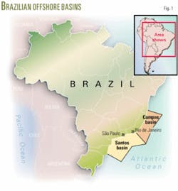
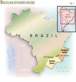
Offshore southeast Brazil, the Santos basin is one of the Brazilian basins that have received considerable industry attention. But active drilling in the Santos basin in recent years has not yet yielded discoveries comparable in size to fields in the Campos basin, the most prolific oil province in Brazil (Fig. 1). Due to its size and its being relative under explored, however, the Santos basin continue to attract interest.2
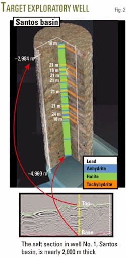
The objective of this study was to plan an exploratory deepwater well (2,140 m water depth) drilled to a depth of 6,000 m TVD in the Santos basin. This section was expected to include nearly 2,000 m of salt rocks, including halite, carnallite, and tachyhydrite (Fig. 2). The target well is the first of four wells to be drilled through the end of 2006.
Before plans are made to drill long salt sections, a thorough knowledge of salt and its properties is necessary.
Salt rocks belong to the group of sedimentary rocks, called evaporites, formed by the evaporation of saline water. Salt is an unusual geologic material because under sustained, constant stress, significant deformation can be expected as a function of time, loading conditions, and physical properties.3 This behavior is called creep.
The rate at which salt will creep depends on temperature, differential stress, and salt type.
Thermal gradient, Santos basin
One of the most important parameters affecting creep rate is temperature.
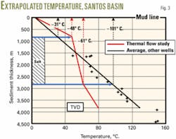
We used two methods to evaluate the temperature gradient in this exploratory prospect. The first was to extrapolate the temperature of the offset wells. For that, we collected 49 temperature values in 20 wells.4 For the deepest section (1,500/4,500 m of sediment thickness), the gradient was determined to be 32º C./km, with BHT reaching almost 160º C.
The second method involved a thermal flow study to evaluate the temperature at the top and at the base of the salt section. The salt has a higher thermal conductivity than the near rock, influencing the thermal gradient of the adjacent formations.
The results in Fig. 3 show some differences in the temperature values. For the purpose of this study, we considered the most pessimistic situation, that is, the highest creep rate, assuming the temperature of the salt section obtained with the first method: top of salt at 31º C. and base of salt at 101º C.
Constitutive equation for salt behavior
Salt rocks exhibit time-dependent deformation when subjected to any level of shear stress due to their crystalline structure. This creep behavior, slow deformation under constant stress, is influenced by the thickness of the salt, formation temperature, mineralogical composition, water content, presence of impurities, and the extent to which differential stresses are applied to the salt body.
Chloride and sulfate salts containing water (bischofite, kieserite, sylvite, and tachyhydrite) are the most mobile. Halite is relatively slow moving, and anhydrite and the carbonates (calcite, dolomite) are essentially immobile.5
Generally, the Brazilian continental margin basins have high geothermal gradients, thick sedimentary sections above salt layers, neo-tectonics inducing salt movement (wellbore breakouts measured), and evidence that salt diapirs are still moving, documented by mapping salt crestal faults in the Campos and Santos basins. Information from wells drilled through deep salt sections show that salt closure can reach high velocities (0.05 in./hr).6
Starting from the early 1990s, creep constitutive laws based on deformation mechanisms were recommended in international technical literature to represent the intrinsic behavior of the material.7-9
The law that incorporates all the portions regarding the deformation mechanisms already isolated was developed by Darrell Munson.7 8 The constitutive equation due to Munson’s creep law considers the following mechanisms:
- Dislocation glide.
- Dislocation climb.
- Undefined mechanism.
The relative contribution of one or another mechanism depends on the temperature and differential stress to which the salt is submitted.
The constitutive equation corresponding to the creep law of double mechanism of deformation is a simplification of the equation developed by Munson and it considers dislocation glide and the undefined creep mechanism. The latter effect was recently identified as being creep along the contacts of the halite grains, provoked by the dissolution of the salt in function of the increase of its solubility, under high pressures at the grain-to-grain contacts.
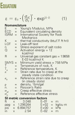
In this article, salt rocks are analyzed assuming elastic-visco-elastic behavior, adopting the double mechanism creep law, as shown in Equation 1 in the accompanying equations box.
Experimental salt tests
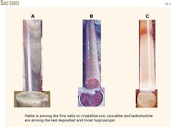
Until last year, only halite and anhydrite were recognized while drilling to subsalt prospects.10 11 The new challenge is to drill through very thick salt layers encompassing different salts, such as carnallite (KCl·MgCl2·6H2O) and tachyhydrite (CaCl2·2MgCl2·12H2O), that exhibit a higher creep rate than halite (NaCl; Fig. 4).
This motivated a new salt sampling, performed in wells in northeast Brazil (Sergipe State).12 13 Special procedures were adopted for sampling, storing, and testing the samples due to the water affinity of the highly hygroscopic salts. Creep tests were performed on specimens with a length-diameter ratio of two, following ISRM standards, at the Laboratory of Rock Mechanics and Rock Hydraulics at IPT-Institute for Technological Research of the State of São Paulo, Brazil.14 15
Experimental results
Three important stages of salt creep behavior must be handled appropriately when material model parameters are evaluated in the laboratory.
A typical creep curve for salt includes two or three stages. After being subjected to stress, the strain rate in salt is very high (transient stage). The rate then decreases monotonically with time until a constant rate of strain is observed (steady-state creep stage). A third, tertiary creep stage then becomes evident. This is characterized by acceleration of the creep rates that cause dilation, an increase in volume through micro fracturing, which leads to failure.
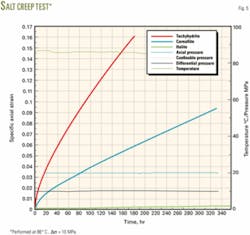
Fig. 5 shows a typical behavior of salt creep. In these tests, tachyhydrite, carnallite, and halite are submitted to a 10-MPa differential stress at 86º C. Before the 160 hr test, the specific axial strains are 0.15 for tachyhydrite, 0.055 for carnallite, and 0.0014 for halite. With these test parameters, tachyhydrite is about 107 times most mobile than halite and about 2.7 times more mobile then carnallite.
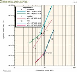
Fig. 6 shows the strain rate results in the steady-state creep stage for separate differential stress ranges (4-20 MPa) from tachyhydrite, carnallite, and halite creep at 86º C. The behavior of tachyhydrite changes the stress exponent (n) from 2.4 to 7.12 after 7-MPa differential stress, and halite changes from 3.36 to 7.55 after 9.9 MPa. Until now, no potential behavior was observed for carnallite, probably because the tests were not complete at this temperature.
Model of well closure
With the creep parameters validated,14 15 we applied the constitutive equation in the numerical simulation of the salt creep behavior to predict the evolution of well closure over time for various mud weights and analyzed several alternative drilling strategies through the salt intervals.
We expected to find a 1,976-m-thick section of salt rocks while drilling this prospect, in the interval from 2,984 m to 4,960 m (WD = 2,140 m; Fig. 2).
Pre and post-processing of the finite-element model was done using a SIGMA system.16 The numerical simulations were performed with the finite-element method and ANVEC code, both Petrobras properties.17 The ANVEC program has extensive application in simulating the behavior of underground excavations,17-21 The program considers non-linear physical elasto-visco-plastic phenomenon, using the constitutive law of double mechanism deformation for creep.
The program demonstrated excellent stability and convergence to predict the creep phenomenon in conditions of high temperature and differential stresses. It simulated the behavior of the well over time as a function of the bit progress using automatic mesh rezoning. This was a big advantage of the program, providing valuable results for drilling operations.10 11 14 15
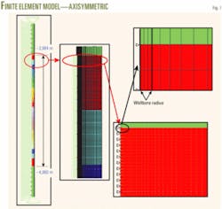
The axisymmetric model, following the longitudinal axis of the well, includes a salt interval of 1,976 m and 200 m of hard rock, below and above the salt layer, to represent the boundary conditions.
We employed 78,408 quadratic, isoparametric elements (with 8 nodes) and 240,043 nodal points in the finite-element model (FEM; Fig. 7). We included different layers to consider the temperature variation with depth and the lithology. As the FEM used the constants isolated in creep tests at 86º C., it was necessary to correct the creep constants by the thermal activation factor (exp(Q/RT0 - Q/RT)).
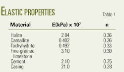
Above and below the salt, the hard rocks with fragile behavior were analyzed using an elasto-plastic model that adopted the plastic flow criteria of Mohr-Coulomb for the multiaxial state of stress. During plastic flow, we assumed isotropic behavior governed by the associative law of plasticity. 17 For the lithostatic column, we assumed an average specific weight of 22.56 kN/cu m. Table 1 summarizes the elastic properties.22
null
Drilling fluid design
Design of the appropriate drilling fluids was based on numerical predictions of well closure.
The behavior of the well was simulated in the time domain, while considering the viscous-plasticity of the salts. The hardware included a P690 IBM Regatta computer with logical partitions, 32 processors (power 4), and 80 GB RAM memory.
We ran numerical simulations to predict the evolution of the well’s closure rate along the longitudinal axis of the wellbore during salt zone drilling and tested several different drilling fluid weights.
To simulate the structural behavior of the well we adopted two strategies:
- Salt layers were drilled in 284 excavation steps, simulating the bit progress in 7 m/hr, in just one single stage.
- Salt layers were drilled in two stages.
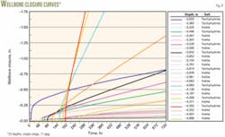
Fig. 8 shows the evolution of wellbore closure over time during a single excavation stage (hole 14¾ in. x 17½in.), using 11-ppg mud weight. Due to irregularities during drilling, 1.75-in. was considered the acceptable limit for wellbore closure, rather than 2.5-in. drift. The curves of wellbore closure with the time of each depth begin when the excavation, in the case the bit, reaches the respective depth.
For example, notice that the curve of wellbore closure in the depth of 4,292 m begins at about 190 hr, immediately after the bit reached that depth. The wellbore closure reached the maximum acceptable value at 300 hr, about 110 hr after first reaching that depth, and about 36 hr after the borehole reached the base of salt.
It’s important to note that the largest closure in the well, among the 25 depths numerical monitored, occurred at 4,292 m, at a point 668 m above the base of the salt. As is expected, the tachyhydrite layers (4,292; 4,208; 4,083; 3,819; 3,632; 3,529; 3,446; 3,363; and 3,033m) have a very high closure rate, and the halite layers have a low closure rate.
We conclude that 300 hr after the beginning of drilling, 11-ppg drilling fluid was not sufficient to keep the wellbore open long enough to complete the drilling operation and set the casing, raising the risk of stuck pipe.
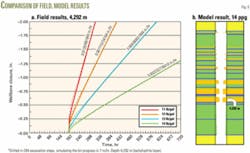
Therefore, we increased the mud weight to 12, 13, and 14 ppg, and we reran the simulations of the wellbore behavior. Fig. 9a shows the summarized results of the wellbore closure with the mud weights 11, 12, 13, and 14 ppg in the deepest tachyhydrite layer at 4,292 m.
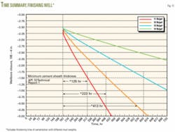
Fig. 9b shows the results of the simulation that used14-ppg mud weight, which appears to allow enough time to finish drilling and set casing without the risk of stuck pipe. To best present the results, Fig. 10 shows the well finishing times, included thickening time of cement at various mud weights.
We also modeled the evolution of the wellbore closure over time as a function of bit progress with 14-ppg mud weight, with the mud weight reduced to 10 ppg when the drillbit reached the base of salt (284 hr), to simulate the rubble zone.23
Reducing the mud weight influences wellbore closure and puts the drill string in jeopardy, as the acceptable closure is reached in just a few hours. Based on this result, the drilling strategy changed.
Preliminary drilling strategy
The new strategy is to drill the well in two stages. The first stage utilizes 14-ppg mud (Figs. 9 and 10). The basic well plan is to drill to 200 m above the base of the salt, before reaching the rubble zone, set casing to avoid losing circulation in the rubble zone, and then, in the second stage, drill the remaining salt layers with 10-ppg mud.
Plan B involves running intermediate casing in the middle of the salt section to isolate particularly soluble salt layers. In Plan B, 14-ppg mud was simulated in the first stage drilling and 10-ppg mud was simulated in the second stage. At 720 hr from the beginning of drilling, the maximum wellbore closure was 1.25-in. during the first stage and 1.50-in. during the second stage.
The two-stage drilling strategy includes:
- Drilling through the thick salt layer with a mud weight of 14 ppg, which especially safeguards against salt creep in the tachyhydrite layers.
- Setting the casing.
- Beginning the second stage of drilling with 10-ppg mud in the less mobile halite layers, which provides enough time to drill the salt, run and set the casing, and avoid stuck pipe and lost circulation.
These numerical results will used during the drilling to guide the operations, so that well closure above the bit does not cause the drill string to get stuck.
The second article in the series will focus on the finite-element modeling and numerical simulation of the casing design and well planning.
References
1. Oliveira, J.E., Idagawa, L.S., and Nogueira, E.C., “Evaporite in Campos Basin: Geological Aspects and Drilling Problems,” Report CENPES-475, Petrobras, Rio de Janeiro, 1985 (in Portuguese).
2. Modica, Christopher J., and Brush, Eugene R., “Postrift sequence stratigraphy, paleogeography, and fill history of the deepwater Santos basin, offshore southeast Brazil,” AAPG Bull., Vol. 88, No. 7, July 2004, pp. 923-945.
3. Barker, John W., and Meeks, W.R., “Estimating Fracture Gradients in Gulf of Mexico Deepwater, Shallow, Massive Salt Sections,” paper No. 84552, SPE Annual Technical Conference and Exhibition, Denver, Oct. 5-8, 2003.
4. Falcao, Jose L., “Drilling in High-Temperature Areas in Brazil: A Wellbore Stability Approach,” paper No. 69516, SPE Latin American and Caribbean Petroleum Engineering Conference, Buenos Aires, Mar. 25-28, 2001.
5. Barker, John W., Feland, K.W., and Tsao, Y.H., “Drilling Long Salt Sections Along the U.S. Gulf Coast,” paper No. 24605, SPE Annual Technical Conference and Exhibition, Washington, DC, Oct. 4-7, 1992.
6. Amaral, C.S., Costa, A. Maia, Gonçalves, C.J. de Castro, and Fonseca, C.F., “Reavaliação do Comportamento do Poço 1-RJS-480 por ocasião do Fechamento do Revestimento de 9 5/8-in. no Trecho de Travessia da Zona de Sal”, Report CENPES/DIPREX/SEDEM-013, Petrobras, Rio de Janeiro, 1999.
7. Munson, Darrell E., Fossum, Arlo F., and Senseny, Paul E., “Approach to First Principles Model Prediction of Measured WIPP (Waste Isolation Pilot Plant) In-Situ Room Closure in Salt,” Tunneling and Underground Space Technology, Vol. 5, 1990, p. 135.
8. Munson, Darrell E., and DeVries, Kerry L., “Development and Validation of a Predictive Technology for Creep Closure of Underground Rooms in Salt,” Seventh International Congress on Rock Mechanics, Aachen, Germany, Sept. 16-20, 1991.
9. Frayne, M.A., and Mraz, D.Z., “Calibration of a Numerical Model for Different Potash Ores,” Proceedings of the Seventh International Congress on Rock Mechanics, Aachen, Germany, Sept. 16-20, 1991, pp. 471-475.
10. Costa, A. Maia, Poiate, Edgard J., Falcão, J.L., Cardoso, C.O., and Rocha, R.S., “Previsão numérica do comportamento do poço 1-RJS-602 durante a travessia da zona de sal e dimensionamento do fluido de perfuração,” Report RT/MC-040, Petrobras, Rio de Janeiro, 2003.
11. Costa, A. Maia, and Poiate, Edgard J., “Previsão numérica do comportamento do poço lua norte 1-RJS-601 durante a travessia da zona de sal e dimensionamento do fluido de perfuração”, Report RT/MC-179, 2003, Petrobras, Rio de Janeiro.
12. Poiate, Edegard J., Costa, A. Maia, and Garske, R.B., “Acompanhamento de testemunhagens de carnalita do poço 7-CP-1498-SE,” Report RT/MC-034, Petrobras, Rio de Janeiro, 2004.
13. Poiate, Edgard J., Costa, A. Maia, and Garske, R.B., “Äcompanhamento de testemunhagens de taquidrita do poço 7-SZ-433-SE,” Report RT/MC-035, Petrobras, Rio de Janeiro, 2004.
14. Costa, A. Maia, and Poiate, Edgard J., “Acompanhamento dos ensaios de fluência sobre amostras de rocha halita -Projeto 600102-período de julho a outubro de 2002,” Report RT/MC-009, Petrobras, Rio de Janeiro, 2003.
15. Costa, A. Maia, Poiate, Edgard J., and Falcão, Jose L., “Triaxial Creep Tests in Salt Applied in Drilling Through Thick Salt Layers in Campos basin-Brazil,” paper No. 92629, IADC/SPE Annual Drilling Conference, Amsterdam, Feb. 23-25, 2005.
16. Amaral, C.S., Costa, A. Maia, Carvalho, M.T.M., and Lira, W.W.M, “Descrição do Sistema SIGMA-Sistema Integrado em Geotecnia para Múltiplas Análises,” Agreement TeCGraf/PUC-Rio-CENPES/Petrobras, Rio de Janeiro, 1996.
17. Costa, A. Maia, “Uma Aplicação de Métodos Computacionais e Princípios de Mecânica das Rochas no Projeto e Análise de Escavações Subterrâneas Destinadas à Mineração Subterrânea,” Tese de Doutorado, COPPE/UFRJ, 1984.
18. Costa, A. Maia, D’Elia, P.D., Moreira, L.F.R., and Coelho, L.C., “Estudo de Mecânica das Rochas e Dimensionamento dos Painéis de Lavra da Camada Inferior de Silvinita da Mina de Sergipe,” Report CENPES/DIPREX/SEDEM RE-013, Petrobras, Rio de Janeiro, 1990.
19. Costa, A. Maia, “Análise da Influência da Espessura de Laje de Silvinita e Carnalita Sobrejacente à Taquidrita em Inibir a Fluência da Taquidrita,” technical report to Vale do Rio Doce Co. RT-CVRD003, Rio de Janeiro, 1995.
20. Costa, A. Maia, “Simulação do Comportamento de Fluência do Painel D1 e Câmara Experimental C1D1, Dimensionamento do Painel de Lavra para a Camada Inferior de Silvinita da Mina de Janeiro, 1995.
21. Costa, A. Maia, “Reavaliação do Comportamento do Painel de lavra I4a da Mina de Potássio de Taquari-Vassouras,” technical report to Vale do Rio Doce Co. RT-CVRD 01, Rio de Janeiro, 200l.
22. Filho, V.M., and Costa, A. Maia,”A técnica de Sísmica de Transmissão Direta na Obtenção de Parâmetros Elásticos de Maciços Rochosos com Aplicação em Projetos de Escavações Subterrâneas,” Second Underground Meeting, Rio de Janeiro, 1985.
23. Fredrich, Joanne T., Coblentz, David, Fossum, Arlo F., and Thorne, B. Joe, “Stress Perturbations Adjacent to Salt Bodies in the Deepwater Gulf of México,” paper No. 84554, SPE Annual Technical Conference and Exhibition, Denver, Oct. 5-8, 2003.
The authors
Edgard Poiate Jr. (poiate@ petrobras.com.br) is an equipment engineer at the Petrobras Research & Development Center (CENPES) in Rio de Janeiro. He has an MS (2001) in mechanical engineering from the State University of São Paulo (UNESP) and is currently enrolled as a PhD student at the University of São Paulo (USP), involved in research in rock and computational mechanics applied in drilling through and near salt.
Álvaro Maia da Costa (amcta @petrobras.com.br) is a civil engineer and manager of scientific methods at the Petrobras Research & Development Center in Rio de Janeiro. He earned an MS (1978) and a PhD (1984) in civil engineering at the Federal University of Rio de Janeiro (UFRJ).
José Luiz Falcão (jfalcao@ petrobras.com.br) is a petroleum engineering consultant for Petrobras E&P in Rio de Janeiro. He has an MS (1991) from the University of Campinas (UNICAMP) and a PhD (1998) from the Colorado School of Mines, both in petroleum engineering.
