Method estimates collapse strength of worn casing
New equations for calculating the collapse strength of worn casing can aid future casing string design.
During any drilling, it is inevitable that drill pipe rotation and tripping will cause casing wear, which can lead to tubular failures. Casing wear is a severe problem that reduces casing string performance, especially collapse resistance, threatening well safety.
Casing string design that considers the effect of wear on casing collapse resistance is the main way to prevent collapse of worn casing. Estimating the remaining collapse strength of worn casing is essential.
This article presents a new equation for predicting the remaining collapse strength of worn casing. The equation was verified by full-scale collapse testing on three samples of worn casing.
Calculating collapse strength
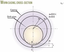
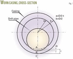
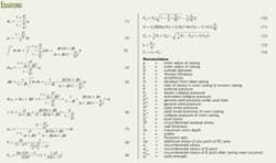
During drilling, friction develops between the drill pipe and casing. Fig. 1 shows a cross-section of a cylindrical model of worn casing. When casing is subjected to an external pressure, P, the circumferential stress on casing can be expressed by an algebraic form of the Lamé equation (Equation 1).1
Note that the longitudinal and circumferential stresses inside the pipe are not equal. Laplace’s law shows that the circumferential stress is twice as high as the longitudinal stress.
Stress is directly proportional to the radius of the pipe. The maximum stress occurs across the inner wall of casing (when r = a). When the circumferential stress of the inner wall of casing equals the yield strength of the material, σθ, σsthe external pressure on the casing is defined as the onset yield pressure, Ps (Equation 2).
Equation 3 calculates the sum of circumferential stresses of the area AB in the radial direction.
Assume that a worn depth, Δt, develops from Point A to Point B (Fig. 1). Equation 4 calculates the circumferential stress at Point B, inside the casing wall, before wear takes place.
Next, we analyze the cross-sectional area, AC, corresponding to the maximum worn depth, t. Assuming that the circumferential stress on area AB before wear occurred is distributed equally to the remaining wall thickness area, Equation 5 calculates BC, the additional stress of any point of area BC.
Then, the circumferential stress, σθBw, on Point B after casing wear occurs is calculated by Equation 6.
When the circumferential stress of Point B equals the yield strength of the material, that is, σθBw = σs the onset yield pressure, Psw, of worn casing is calculated by Equation 7.
First, we evaluate the collapse pressure of unworn casing. Toshitaka Tamano and others from Japan’s Nippon Steel Corp.2 developed an empirical formula for estimation of actual unworn tube collapse strength (Equations 8-12).
Next, we evaluate the collapse pressure of worn casing, pw, using Equations 13 and 14.
Comparison with tests
To validate Equation 14, full-scale collapse testing of worn casing was performed at the Tubular Goods Research Center in Xi’an, China.
For the testing, we selected standard P110 grade casing (minimum yield strength 110,000 psi; maximum yield strength 140,000 psi) with diameter (Φ) 244.5 mm x 11.99 mm.
Tables 1, 2, and 3 show, respectively, dimensions of the geometry, mechanical performance, and worn size of the samples.
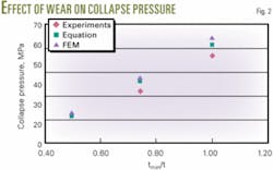
The collapse test was done in a full-scale collapse machine. The sample was subjected to loading equal to external pressure. Fig. 2 shows the comparison of the estimated and experimental results under pure external pressure. The estimated pressure indicates the same trend for wear ratio as experimental results and is in good agreement with experimental pressure.
Comparison with FEM
Finite element method (FEM) analysis on worn casing collapse strength was done with Nastran software from MSC Software Corp. The data used in the analysis were from measured results of the casing samples. Fig. 2 includes the results of FEM analysis. The estimated pressures and results of FEM analysis are almost all in good agreement with experimental results.
After investigating casing wear caused by drill pipe rotation, we built a model for casing wear and derived the equations for worn casing collapse strength. Comparisons of the estimated pressure, the results of FEM analysis, and the experimental results indicate good agreement. The new equation will provide a basic for casing string design that takes into account the effect of wear on casing collapse strength. ✦
References
1. Zhilun Xu, “Elasticity Mechanics,” 3rd edition; Beijing: Higher Education Press, 2000.
2. Tamano, T., Mimaki, T., et al., “A New Empirical Formula for Collapse Resistance of Commercial Casing,” Proceedings of the Second International Offshore Mechanics and Arctic Engineering Symposium, in conjunction with the ASME/ETCE Conference, Houston, 1983, p. 489.
The author
Gao Zhihai ([email protected]) is a senior engineer at the Tubular Goods Research Center, Xi’An, China. He has engaged in research on mechanical and environment behavior of oil tubular goods. Gao is currently studying for his doctoral degree at Xi’an Jiaotong University, Xi’an City, China.


