Latest revision to API gas-measurement standard identifies sample distortion sources
Revision of Chapter 14.1 of the API Manual of Petroleum Measurement Standards (MPMS) was published in June 2001.
This revision is the result of 7 years of an extensive natural gas sampling methods research program at the Gas Research Institute's Metering Research Facility at the Southwest Research Institute in San Antonio. GTI co-sponsored the research along with API and the Minerals Management Service of the US Department of Interior.
The revision provides guidance for obtaining representative samples of natural gas through spot, composite, and continuous sampling methods.
It focuses on the practical application of thermodynamic principles that, if ignored, can cause a gas sample to become distorted, resulting in a biased gas analysis.
If a biased analysis is used to calculate the heating value or other properties of the sampled gas, errors of more than 10% may occur.
This article draws on the information in the revised Chapter 14.1 and presents an overview of three common causes of gas sample distortion:
- Equipment and processes that cause the sample gas' temperature to drop below the hydrocarbon dew point temperature.
- Dirty or contaminated sampling systems.
- Sampling system components fabricated from materials known to affect the integrity of a natural gas sample.
The article also presents recommendations for avoiding gas sample distortion according to the revised Chapter 14.1.
The API Chapter 14.1 working group, a research steering committee consisting of natural gas sampling experts from major oil and gas companies, provided input that helped focus the project on improving current field practices.
The standard is suitable as an instructional tool and as a guide to sampling-system design and sampling techniques.
Written primarily for field personnel, the standard provides the technical background necessary to understand and apply basic hydrocarbon mixture thermodynamics to natural gas sampling in order to avoid gas sample distortion.
Hydrocarbon dew point
The hydrocarbon dew point is the pressure and temperature at which hydrocarbon constituents in a natural gas mixture begin to change phase.
For instance, if the temperature of a natural gas mixture is reduced while the pressure remains constant, the temperature at which hydrocarbon condensation begins to occur is the hydrocarbon dew point temperature. This process is known as an "isobaric" (or constant pressure) temperature reduction. It is the process that occurs when a "chilled mirror device" is used in the field to determine dew point.
If the pressure of a natural gas is increased while the temperature remains constant, the pressure at which hydrocarbon condensation begins is the hydrocarbon dew point pressure. This process is also known as an "isothermal" (or constant temperature) pressure increase and is similar to processes used for determining dew point in a laboratory.
The hydrocarbon dew point of a natural gas differs from the water dew point in that the latter describes the pressure and temperature at which water vapor contained in the gas mixture begins to condense. Some gas mixtures will reach the water dew point temperature before reaching the hydrocarbon dew point temperature during an isobaric temperature reduction.
This article focuses on the hydrocarbon dew point because of its influence on heating value. This distinction should be kept in mind during any discussion of natural gas thermodynamics.
Retrograde condensation, a phenomenon that occurs in many common natural gas mixtures, is characterized by the presence of two hydrocarbon dew points at a given pressure or temperature. Retrograde condensation can occur during isobaric temperature increases or during isothermal pressure reductions. Retrograde behavior is characteristic of natural gas and should be considered when sampling a natural gas stream and when designing gas-sampling systems.
Phase diagram
A phase diagram or phase envelope describes the phase change behavior of a natural gas mixture. It can be used to illustrate the effect of natural gas sampling processes on natural gas.
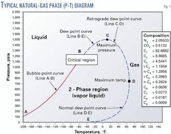
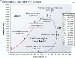
Fig. 1 shows a typical phase diagram for natural gas. Line A-B is the bubble-point curve. The bubble point is reached when an infinitesimal amount of gas appears during an isothermal pressure reduction of a liquid hydrocarbon mixture.
Line B-E, the dew point curve, represents the range of pressures and temperatures at which gas-liquid phase changes occur with a natural gas mixture.
The points along Line B-D represent the pressures and temperatures at which retrograde condensation occurs. Retrograde condensation can occur during common natural gas sampling processes.
Line D-E is the lower or normal dew point curve. Condensation associated with the conditions defined by this curve may occur during a pressure increase, such as when compressing a gas sample from a vacuum gathering system into a sample cylinder.
Dew point and sampling
The hydrocarbon dew point is perhaps the single most important property in natural gas sampling.
If the sample temperature is allowed to drop below the hydrocarbon dew point temperature, a significant loss in hydrocarbon content can occur, resulting in errors in volumetric flow rate, heating value, and other gas property calculations.
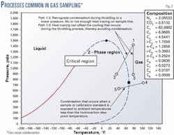
Tests conducted at Southwest Research Institute on spot sampling methods showed that the impact of dropping below the hydrocarbon dew point temperature contributes to increased random and bias error in the calculated heating value and density. The phase diagram shown in Fig. 2 illustrates how different processes common in natural gas sampling can cause the temperature of the sampled gas to fall below the hydrocarbon dew point.
Path 1-2 represents the process that occurs when natural gas flows through a regulator or partially closed valve. The cooling associated with the pressure reduction is known as the Joule-Thomson effect. Condensation and sample distortion can occur during this "throttling" process.
The cooling can be offset through application of heat to the sampling system. The 2001 revision of Chapter 14.1 recommends that 7° F./100 psi of pressure drop should be applied in addition to any heating required to maintain the system 20-50° F. above the hydrocarbon dew point temperature.
Path 1-3 shows the potential effect of adding sufficient heat to the system to offset the cooling effect. Path 4-5 shows how condensation of a sample can occur if the sample container is exposed to an ambient temperature below the hydrocarbon dew point temperature.
Effect of phase change
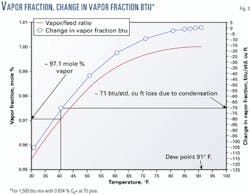
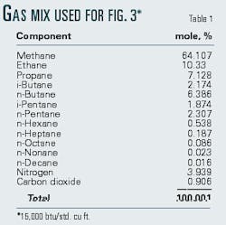
The potential impact of condensation on the heating value of natural gas can be illustrated graphically. Fig. 3 shows the potential effect of 41° F. gas sampling equipment on a 1,500-btu natural gas with 0.85 mole % n-hexane through n-decane (C6+) components and a hydrocarbon dew point of 91° F. Table 1 shows the gas composition associated with the figure.
The vertical axis on the left shows the vapor (gas) fraction, on a molar basis. The liquid fraction is simply 1 minus the vapor fraction. The vertical axis on the right shows the change in vapor fraction btu.
As the temperature is reduced below the hydrocarbon dew point temperature, hydrocarbon constituents condense in order of decreasing molecular weight. This condensation causes the vapor fraction of the mixture to decrease and a corresponding decrease in the heating value of the vapor fraction.
As the gas temperature is reduced below the hydrocarbon dew point, there is a large decrease in heating value associated with a small amount of liquid condensation. At a temperature of 41° F., the loss in heating value amounts to more than 70 btu/std. cu ft. The mass and weight of liquid produced by condensation of the natural gas in Fig. 3 can be estimated. Assume that a representative sample of natural gas is contained in a standard 300-cc constant volume sample cylinder and the temperature is reduced to 41° F.
Such a reduction causes condensation to occur, and the vapor fraction decreases by approximately 2.9 mole %. The percentage decrease in the mass of the vapor fraction for this particular gas mixture is 7.5%. The total mass of gas (vapor) at 75 psia and 91° F. is approximately 0.0045 lbm. If 7.5% of the mass condenses, then the mass of liquid contained in the cylinder will be approximately 0.00034 lbm.
The weight of the liquid is approximately 0.011 lb, or slightly less than the weight of a 25¢ coin. This small amount of liquid can account for significant losses in gas sample heating value, but it is difficult to detect without sensitive laboratory instruments. The process described is similar to the process shown by Path 4-5 in Fig. 2 and illustrates how a phase change can cause a decrease in heating value.
Now consider a very small amount of condensed hydrocarbons (weighing slightly less than a 25¢ coin) within a component of a sampling system, such as a sample valve. This could occur during the pressure reduction described by Path 1-2 in Fig. 2. If the small amount of condensed hydrocarbons is swept into the sample cylinder during sampling, a significant increase in heating value can result.
This discussion illustrates the magnitude of the impact of phase changes on natural gas samples. In practice, the effect of a distorted gas sample on calculated gas properties is very difficult to predict. The effects of poor sampling technique on gas samples taken under actual laboratory and field conditions are far more complicated and cannot be accurately predicted using current technology.
Sample distortion: temperature less than dew point
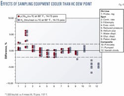
The Gas Processors Association spot sampling methods and three composite samplers were tested with several gravimetrically prepared natural gas mixtures in static (non-flowing) conditions. Fig. 4 shows the deviations in calculated heating value and density for the gas samples obtained during the tests.
When the temperature of the sampling hardware was less than the hydrocarbon dew point, all methods produced distorted gas samples. Some sampling methods produced samples that were enriched, causing an increase in the sample heating value and density. Other methods produced samples that were depleted, causing a decrease in the sample heating value and density. All of the methods produced highly variable results, suggesting that a phase change occurred during sampling.
The results from the composite sampler tests in Fig. 4 (Methods 10, 11, and 12) led to subsequent field tests better to understand the operational limits of composite samplers. In situ tests were conducted at a Questar Corp. gas pipeline site in northwest Colorado.
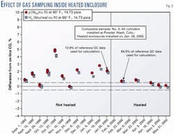
Four composite samplers were installed on a pipeline that was flowing 1,100 btu/std. cu ft natural gas and exposed to ambient conditions 60-70° F. below the hydrocarbon dew point. The composite samples were analyzed and the calculated heating value and density of each sample were compared to the average values acquired from on-line gas chromatograph analyses. After approximately 6 months of testing, heated enclosures were installed on the composite sampling systems to stabilize the ambient air temperature around the samplers at approximately 100° F.
Fig. 5 shows test results from one composite sampling system. Results after the heated enclosures were installed showed a significant improvement, with each system providing samples with heating values and densities that agreed with the reference to within ±0.75%, nominally.
The 2001 revision of Chapter 14.1 states that the sample gas temperature must remain 20-50° F. above the hydrocarbon dew point temperature at all times during sampling. If the sampling process involves a pressure reduction, additional heat must be added at or upstream of the point of pressure reduction to offset the Joule-Thomson effect (approximately 7° F./100 psi of pressure decrease).
Chapter 14.1 recommends the use of steam, hot water, or electrical heat tracing, catalytic heaters, and insulation to provide heat to the sample gas. If the ambient temperature will keep the sample gas at 20-50° F. above the hydrocarbon dew point temperature, heating is not required.
If sample cylinders are exposed to temperatures below the hydrocarbon dew point temperature after sampling (Path 4-5 in Fig. 2), the sample can be recovered by heating it to 140° F., or 20-50° F. above the hydrocarbon dew point temperature for at least 2 hr before analysis.
Sample distortion: contaminated systems
The previous discussion showed that the presence of liquid hydrocarbons affects the integrity of a natural gas sample. Liquid hydrocarbon contaminants are not always natural gas constituents. Occasionally, heavier hydrocarbons contained in compressor or machine oil contaminate sampling equipment.
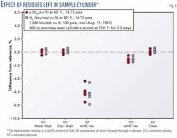
Fig. 6 shows the impact of several residues left in a sample cylinder. The hydrocarbon residue is a 50/50 mixture of SAE-30 compressor oil and n-hexane through n-decane. The liquid hydrocarbon residue caused a reduction in the heating value and density of the gas sample.
If there is reason to believe that any part of the sampling system has been contaminated, the system must be thoroughly cleaned to obtain a representative natural gas sample. Several cleaning methods were tested on contaminated sample cylinders during the research project.
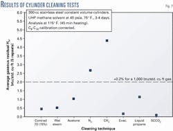
Fig. 7 shows the results of one series of cleaning tests, which indicate that most methods leave some residual. Steam cleaning was the most robust method evaluated during the research.
If a gas sample is taken with a cylinder that has not been sufficiently purged or if air or other contaminants have leaked into the sampling system, then the integrity of the sample will be compromised, even if the sampling method is performed correctly.
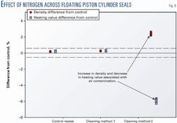
Fig. 8 shows the effect of a nitrogen leak on the heating value and density of a gas sample obtained during sample cylinder cleaning tests at Southwest Research Institute. The nitrogen increases the density and reduces the heating value of the sample.
The errors can be significant and might not have been discovered if only the heating value of the sample were considered. The effect is similar if air is introduced into the system during sampling.
The 2001 revision of Chapter 14.1 recommends that sample systems be designed so that they can be thoroughly cleaned and that a procedure for cleaning sampling systems and sample containers be established. Chapter 14.1 recommends that sample cylinders be cleaned before each sample collection.
Steam is identified as the most effective sampling system cleaning agent. Water containing corrosion inhibitors or other chemicals that may contaminate the sampling system should be avoided.
Solvents, such as acetone and liquid propane, that do not leave a residue after drying are acceptable. Decon Contrad 70, or equivalent, is also acceptable. Other cleaning methods may be used, if testing can prove their effectiveness.
Sample containers and sampling systems must be dried and purged, or evacuated, after cleaning. Nitrogen, helium, and dry instrument-quality air are acceptable for drying sample containers and sampling systems. Blanket gases may be used to pre-charge sample containers. The blanket gas must be selected so that the analytical device will not interpret it as part of the sample.
Sample distortion: materials affecting integrity
Many materials commonly used to fabricate sampling system components can distort gas sample integrity. Highly porous materials and components with large surface areas are likely to cause adsorption or "sticking" of hydrocarbon molecules to the surface of the material, that produce a corresponding reduction in heating value.
If the temperature or pressure of the system changes, adsorbed molecules can be released from the material surface and can re-enter the sample stream, causing an increase in the heating value. Cleaning the sampling system cannot eliminate this phenomenon.
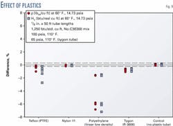
Several common tubing materials of different diameters and lengths were tested to determine the impact on gas sample integrity. Clean stainless steel tubing was found to have little or no impact. Most plastic tubing materials had an impact on sample integrity, with polyethylene causing a reduction in heating value and density of more than 6%.
This is believed to be caused by solid-surface adsorption. Nylon 11 was the only plastic tubing material tested that did not adversely affect the gas heating value and density determination (Fig. 9).
The 2001 revision of Chapter 14.1 recommends the use of inert and non-porous materials in gas sampling systems with 304 or 316 stainless steel generally recommended. Carbon steel is not recommended because of the potential for chemical reactions with the components in the gas that can distort the sample.
Furthermore, carbon steel is susceptible to high corrosion rates, particularly when used in wet or sour gas sampling. The use of dissimilar materials is discouraged because of the potential for high corrosion rates and gas sample distortion.
Valve seats, O-rings, and other types of seals should be made of elastomers that will not degrade in contact with the sample gas. With the exception of Nylon 11 or its equivalent, Chapter 14.1 does not recommend use of plastic tubing in natural gas sampling systems
For sour gas applications, Chapter 14.1 recommends use of special linings or coatings, such as epoxy or other suitable coatings. Soft metals, such as brass, copper, and aluminum are not recommended.
Based on a presentation to the Congreso Internacional de Ductos (Comité Interorganismos de Ductos de Petróleos Mexicanos), Mérida, Yucatán, Nov. 14-16, 2001.
The author
Eric Kelner ([email protected]) is a senior research engineer at the Southwest Research Institute, San Antonio. He has also worked as a design engineer for Questar Regulated Services, Salt Lake City. He has also served as an instructor at the International School of Hydrocarbon Measurement and the American School of Gas Measurement Technology. Kelner holds a BS (1994) in mechanical engineering from the University of Utah and is a member of API, AGA.
