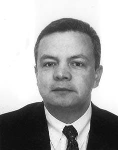
Siegfried Schuler
Mobil Erdgas-Erdol GmbH
Celle, GermanyRene Santos
Mobil Erdgas-Erdol GmbH
Hamburg
Successful completion of a multiple fraced, deep horizontal well demonstrated new techniques for producing tight gas sands.
In Northwest Germany, Mobil Erdgas-Erdol GmbH drilled, cased, and fraced the worlds deepest horizontal well in the ultra-tight Rotliegendes Main sand at 15,687 ft (4,783 m) true vertical depth.
Mobil is the operator for a consortium that includes BEB Erdgas & Erdol GmbH, RWE-DEA AG, and Wintershall AG. The well, drilled to 18,860 ft measured depth, includes a 2,066 ft horizontal section and four hydraulic fracs.1 2 3
The successfully completed well currently produces at a stable rate of 18 MMcfd (20,000 cu m/hr) with a flowing pressure of about 4,350 psi (300 bar) from the four fractures. Cumulative production exceeds 2 bcf (54 million cu m) of gas.
The pilot is the first of its kind ever attempted in an ultratight (0.01-0.02 md), deep (15,700 ft TVD), high pressure (9,000 psi), and high temperature (290 F./140 C.) reservoir.
The multiple frac concept provides a cost-efficient method to economically produce significant gas resources in the ultra-tight Rotliegendes Main sand.
The massive but tight target sand is a member of three productive Rotliegendes reservoirs in the Soehlingen field. Mobil, as operator, began developing Soehlingen in 1982. The tight reservoir has been produced on a limited basis from three vertical wells drilled in the early 1980s and fractured with conventional techniques but with limited economic success.
Besides the satisfactory initial gas production rate, the well established several world records, including deepest horizontal well with multiple fracs, and proved this new technique to develop ultra-tight sands.
Projects objective
The projects objective was to obtain production rates from a multiple fraced horizontal well that are three to five times the rates obtainable from a vertical, conventionally fraced well.
This translates into a sustained rate of about 13 MMcfd.
The targeted Main sand is a member of three productive Rotliegendes sands in the field. The sand is massive (280 ft gross), with moderate porosity (10-12%) but very low permeability (0.01-0.02 md). The presence of late diagenetic illite in the pore space is the cause for the low permeability.
The reservoir area (Fig. 1 [97014 bytes]) is also large, 11 sq miles (28 sq km).
The extreme conditions of depth, bottom hole pressure, and bottom hole temperature demanded careful planning before a project of this magnitude could be undertaken.
Formation evaluation
All available core and log data from nine wells coupled with production tests from three vertical Main sand producers was extensively analyzed. All core-measured permeabilities were converted to in situ conditions and compared with the test-derived permeability values. However, because of the ultra-low permeabilities, the values did not always agree.
In a further investigation, the production history of one vertical, conventionally fraced well was matched to permeability. An in-house frac design/frac prediction program (Hyfrac) provided a 10-year production match.
With the permeability derived from these methods, an isopermeability map was constructed and the Soehlingen Z-10 well was proposed for an area with maximum permeability of about 0.015 md.
Extensive work with different frac direction configurations in an idealized horizontal well showed that optimal gas recovery would be derived by placing the fracs perpendicular to the well bore as opposed to parallel to it. To place perpendicular fracs, one has to know the direction of the maximum stress in the formation. An oriented core taken in a well drilled in the field in 1992 provided this direction.
The oriented core indicated a NW-SE maximum stress direction that was confirmed by other methods such as break-out orientation analysis. Therefore, it was decided to drill the horizontal section in a SW-NE direction to obtain fracs perpendicular to the well bore.
An additional borehole stability analysis indicated that the desired well direction would not cause any major problems during drilling.
The final well location was further optimized by drilling through a giant Zechstein salt plug instead of through sediments (Fig. 2 [14541.gif]). This increased significantly the penetration rate and decreased drilling costs.
After optimizing the location based on permeability predictions, maximum stress direction, borehole stability, and drilling through salt, Mobils next step was to design the hydraulic fracs.
Design basis
Based on the expected permeability of 0.015 md in the proposed location, Mobil used its in-house PC-based Hyfrac program to design the size and number of fracs. The program can design fracs, predict production from fracs, and perform quick economic analysis.
For the expected permeability, the analysis indicated an optimal horizontal length of about 3,300 ft with six perpendicular fracs. The six fracs should produce a total sustained rate of about 15 MMcfd.
Each individual frac would have a frac-propped length of around 330 ft and would be created by pumping 211,000 gal (800 cu m) of high-temperature gel, and 550,000 lb (250 tons) of intermediate-strength proppants at a rate of 35 bbl/min (5.6 cu m/min).
Because the program uses a simplified model for performance predictions (idealized reservoir with constant properties), Mobil used its multipurpose reservoir simulator, Pegasus,4 to gain insight into the interference between fracs and the effects of different drainage areas, and to obtain a more accurate performance prediction.
The simulator incorporates the horizontal well equations of Babu-Odeh.5 As expected, the more rigorous simulator helped us to obtain better predictions of well performance and also provided insights into frac interference and the unequal contribution from each frac. The outer fracs produce more than the inner fracs.
Drilling
The well was drilled in about 8 months. The Z-10 well has a total displacement of 4,370 ft. The slightly inverted horizontal section of 2,066 ft at 92 inclination runs parallel and about 164 ft below the top of the payzone.
A large casing scheme was used to obtain the required 838-in. open hole size in the reservoir (Fig. 5 [64237 bytes]).
The horizontal section had to be cased and cemented with a 7-in. production liner and connected to a 7-in. tie-back string to surface.
Intensive torque and drag simulations were carried out to ensure reaching the targeted depth. One major consideration was to keep the top hole vertical. Down to the kickoff point (KOP), plans called for an inclination below 1.
Therefore, the 16-in. and 1212-in. hole sections were drilled directionally with measurements-while-drilling (MWD) surveillance. To have enough backreaming and hole cleaning capacity, Mobil selected a rig equipped with a top drive. The KOP was picked at 12,366 ft TVD within the salt section. A moderate build-up rate (BUR) of 1.5/100 ft resulted in an inclination of 40 at the 958-in. casing shoe (15,186 ft) located at the base of the salt.
Based on results from a partner well, the drilling of the hard, abrasive Rotliegendes formation required a long radius curvature with a BUR of 4.5/100 ft. A tangent section at 60 inclination was included in the bent section to compensate for potential problems (differential sticking) in the partially depleted Wustrow sand above the target horizon.
The directional drilling was done with steerable motors, and an MWD tool was run for orientation and surveying. Careful analysis of the drilling progress supported by cutting cores and proper directional control kept the well bore within the specified target windows.
While drilling the first part of the horizontal section, the drilling assembly became differentially stuck at 17,131 ft.
Various attempts were made to free the drillstring. Finally, the well was plugged back and sidetracked. Because of these difficulties, Mobil changed the mud system and drilled the remainder of the hole with oil-based mud at a reduced mud weight.
Another change in the well plan was to reduce the horizontal section from 3,280 to 1,968 ft. This was possible because the permeability at the top of the Main sand based on core data was better than expected, 0.02 md vs. 0.015 md. Consequently, the number of fracs could also be reduced from six to four (Fig. 3 [75476 bytes]).
After the sidetrack and partial redrill, drilling continued to the TD of 18,860 ft without significant problems.
The well was logged (DSI-NGT-6CAL) using TLC-equipment (Fig. 4 [52141 bytes]). The borehole caliper showed a slightly enlarged but almost gauge well bore.
The 7-in. production liner was run without any problems. The liner had bow-type, semi-rigid centralizers for a greater than 80% stand-off. Also, aluminum spiral rigid centralizers were placed in the frac intervals.
Cementing was done with a slurry with no free water and settling. Optimum displacement was obtained by pumping a spacer-train in turbulent flow. A complete hydraulic seal of the annulus was obtained, although it was not possible to rotate the liner during cementing as planned.
Completion
The completion and stimulation operations took about 5 months before the well went on regular production. The completion design using the drilling rig with top drive was based on following considerations:
- Capability to produce and isolate each frac separately
- Use of two work (perforate and isolate) and treatment strings (test and stimulate)
- Separate round trips to perforate, stimulate, and isolate each frac interval
- Open annulus to monitor bottom hole pressures during fracture treatment
- Sized salt mud as a completion fluid
- 134-in. coiled tubing to clean out well and operate frac isolation equipment.
The first interval was to be perforated (2 ft of 412-in. gun, 12 jet shots/ft) with a dual perforating and positioning system. Annulus pressure fired one gun and tubing pressure fired the other. The plan called for 48 big holes (0.7 in.).
The anchor and annular gun worked as designed, but the tubing gun failed to fire because of salt and debris plugging the firing head.
It was decided to frac with 24 holes rather than the designed 48.
The frac was completed successfully. Therefore, the anchor system was not used in subsequent jobs.
For overbalanced perforating, about 1,640 ft of nitrogen were circulated into the annulus that was pressured to 7,500 psi. This created a bottom hole pressure of about 16,000 psi (4,100 psi above the frac gradient).
This technique can obtain good fracturing results with low near-well pressure losses (low tortuosity, such as avoiding multiple and non-planar fractures).
The isolation equipment became stuck during the completion of the fourth frac interval. Several attempts were made to pull the assembly, but eventually it had to be milled. An extreme overbalance perforating job was performed on a fifth zone.
An additional 167 ft of perforations over a 266 ft interval were added to take advantage of the higher permeability close to the top of the Main sand.
Stimulation operations
The first hydraulic fracture treatment consisted of a breakdown and step-down test to establish communication at the highest rate possible. For pressure measurement the annulus was open.
The maximum pressure recorded was 15,600 psi. The testing phase checked the frac design assumptions (such as initial shut-in pressure, ISIP, and fracture closure pressure, FCP) and determined the magnitude of downhole pressure restrictions (tortuosity).
Two proppant erosion slugs were used to remove tortuosity. This reduced treatment pressure including a drop in the ISIP. A minifrac was included in the first frac job to determine the fluid leak-off coefficient, treatment efficiency, and to finalize the treatment design.
The main treatment consisted of 135,800 gal of crosslinked borate system fluid and proppant weight of 530,000 lb of intermediate-strength proppant. This included 26% resin-coated proppants (RCP) to minimize any proppant backflow.
The treatment was pumped at an average rate of 35 bbl/min. The proppant concentration was ramped from 1 to 10 ppg (0.12 to 1.2 kg/l.). A slight indication of a tip screenout was observed.
Forced closure procedure was used to accelerate fracture closure in the entry area to improve the quality of the proppant packing around the borehole.
To achieve a designed frac length of 350 ft, each fracture contained an average of 550,000 lb of proppants pumped in about 132,000 gal of crosslinked high-temperature borate gel.
Based on the experience of the individual treatments, the pad volume for Fracs 2, 3, and 4 was continuously reduced, to minimize the liquid loading and to increase the tendency for tip screenout. Also, the number of erosional stages was reduced and the maximum proppant concentration increased to 12.5 ppg.
From the observations and analysis of all fractures it was concluded that:
- All fracturing operations were successfully completed.
- Frac height was contained in the Main sand.
- Overbalanced perforating resulted in low initial well bore friction. This friction was further reduced by erosion stages.
Production results
After the first fracture treatment, test of the interval confirmed the fracturing approach. With coiled tubing and nitrogen for artificial lift, the well, after a couple of days, produced 2.3 MMcfd at a well head flowing pressure (WHFP) of 1,160 psi. This test showed that the well flow back was slow. However, on the whole the production trend was positive.
After having completed the well with four fractures, the well was brought on stream in January 1995. In the first 6 months, it produced 2.2 bcf of gas.
After a short clean-out period and producing from the lowermost two fractures, the well tested 9 MMcfd with a 1,305 psi WHFP.
Because the effect of fracturing a very tight reservoir in a horizontal well is relatively unclear, the production behavior was thought to be rather complex and difficult to interpret. Traditional drawdown and build-up testing is not practical because of the very low permeability. Nevertheless, it was concluded that the productivity was impaired by well bore damage because of inflow performance tests at different drawdowns and the effect of fines, which were observed in the load water.
The produced fines were formation particles (quartz, feldspar, and illite/chlorite) as well as organic residue from the frac and completion fluid.
A small acid wash helped to increase the production to 16 MMcfd at a 5,450 psi WHFP.
After the remaining two other fractures were opened, the well produced from all four fractures. During a short cleanup period the production was increased to 19.6 MMcfd at a 5,045 psi WHFP.
Finally, after a second acid wash on all fractures, proppant-free production reached a peak rate of 25 MMcfd at a 4,350 psi WHFP.
Only 15% of the frac fluid was produced back and about 1% of proppants injected were found in the well stream. The relatively low cleanout volume of the fractures is attributed to fluid leakoff during the lengthy completion time.
The low amount of proppant produced back is because of an efficient resin-coated proppant pack.
The well currently produces from all four fracs at a stable rate of 18 MMcfd with a flowing tubing pressure of about 4,350 psi (Fig. 6 [62156 bytes]).
A deeper understanding of the performance behavior was obtained by a model, matching certain conditions of the production history with respect to rate, well flowing pressure (WFP), and cumulative gas produced.
An analytical model that can represent the dynamic behavior of multiple fractures producing via a horizontal well was used. The following model parameters resulted in an optimum match: Four fractures with an effective wing-length of 230 ft (efficiency of 0.66 for a targeted length of 350 ft and a reservoir permeability of 0.02 md).
Technology demonstrated
The Soehlingen Z-10 well accomplished its objectives. Besides satisfactory production rate, reserves and economics, the well established several first applications including deepest horizontal well with multiple fractures.
The Z-10 demonstrated that it is technically feasible to drill, complete, and have multiple stimulation in a 2,066-ft long horizontal section in a very deep, ultra-tight reservoir, under extreme high pressure/high temperature operating conditions.
After cleanup and selectively testing individual hydraulic fractures the actual productivity from four fractures is four times that of a conventionally fractured vertical well.
The pioneering project provided evidence that the integration of horizontal well and stimulation techniques will mobilize new reserves from very low permeable gas reservoirs. Above all, this represents a breakthrough for the future development of tight gas sands.
The results of the well confirm that a significant part of the Main sand can be made economically producible, especially when the horizontal multifrac well can be drilled and completed at lower cost and higher technical efficiency.
It is expected that this technology will play an increasingly important part in developing tight gas sands and also in more permeable reservoirs for higher productivity and better economic results.
References
1. Pust, G., and Schamp J., Soehlingen Z-10: Drilling Aspects of a Deep Horizontal Well for Tight Gas, Paper No. SPE 30350, Offshore Europe Conference, Aberdeen, 1995.
2. Chambers M.R., Mller, M.W., and Grossmann A., Well Completion Design and Operations for a Deep Horizontal Well with Multiple Fractures, Paper No. SPE 30417, Offshore Europe Conference, Aberdeen, 1995.
3. Abou-Sayed, I.S., Schueler, S., Ehrl, E., and Hendriks, W., Multiple Hydraulic Fracture Stimulation in a Deep Horizontal Tight Gas Well, Paper No. SPE 30532, SPE Annual Technical Conference, Dallas, 1995.
4. Walker, R.F., Ehrl, E., and Arasteh, M., Simulation verifies advantages of multiple fracs in a horizontal well, OGJ, Nov. 29, 1993, p. 66.
5. Babu, D.K., and Odeh A.S., Productivity of a Horizontal Well, JPT, November 1989, p. 417.
The Authors
Siegfried Schler is a senior reservoir engineering advisor with Mobil Erdgas-Erdol GmbH (MEEG) in Celle, Germany. He has worked for Mobil on various engineering, operating, and planning assignments in Germany and abroad. Schler has an MS in mining engineering from the Technical University of Berlin. He is a member of SPE.
Copyright 1996 Oil & Gas Journal. All Rights Reserved.


