Study links iron sulfide to MEG column burping
D.R. Babu
DHST Consultants
Bengaluru, India
M. Hosseinzadeh
South Pars Gas Co.
H. Akbary
Petropars Ltd.
Tehran
Iron sulfide (FeS) particles entrained in formation water are small (< 1 μm) with a very large surface area. When freshly produced FeS contacts hydrocarbon condensates they create stable emulsions that are carried all the way to monoethylene glycol (MEG) still columns and likely cause burping in these columns.
Burping occurs in the still columns of MEG loops when condensate carried to the re-boiler results in very high vapor velocities followed by collapse of packing. Deposition of scales on the internals of the column always accompanies burping. This article looks at similarities between such occurrences in South Pars and Bass Straits gas condensate production and transportation.
Increased deepwater production has spurred a rise in mono ethylene glycol (MEG) as a hydrate inhibitor. Seabed temperatures of 2-5° C. require any proposed hydrate inhibitor to offset subcooling levels of about 14° C. or more. Recently developed kinetic hydrate inhibitors are not effective beyond subcooling levels of 12° C.
Using dissolved salts in formation water as hydrate inhibitors requires rarely encountered salinity levels of 300,000 ppm for deepwater applications, with the availability of formation water particularly uncertain during early production. MEG, which is cheap and readily available due to its extensive use in other industries, is an obvious alternative. When mixed with produced fluids at the entrance of subsea pipelines at concentrations of 50% wt. or more it can depress hydrate formation temperature to the required subcooling levels.
MEG recovery occurs in the separated aqueous phase of the received fluids and, after evaporating the water in the regenerators, is recycled to the pipeline for reuse, completing the MEG loop. MEG loops are a common feature of most natural gas projects in the North Sea and Gulf of Mexico.
Operating an MEG loop, however, has never been smooth. Solids and black pasty materials precipitate in various unwanted and unforeseen places in the loop, creating operating problems.1-5 Five operators of gas condensate assets in Bass Straits off southern Australia faced identical problems with their MEG loops.6 In addition to continuous deposition of scales on the internals of the still columns, they reported significant amounts of condensate carry-under into the still columns in the form of a stable condensate-rich MEG emulsion.
When highly volatile condensate reaches the reboiler of a still column the large volume of hydrocarbon vapor generated kicks up a liquid slug, damaging the bed and moving its supports and limiters out of position, often bringing down entire packing sections. This destructive event is called column burping.
A similar event occurred in one of the South Pars projects in the Persian Gulf after only a few months of production. Though until now unreported, this event seems to mirror the day-to-day problems encountered by Bass Straits operators.
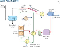
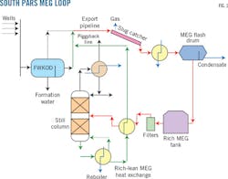
Fig. 1 shows a typical MEG loop used in South Pars development projects. Free water from wells is separated in free-water knock out drums (FWKOD) and treated in an oily water treatment plant (OWTP) before discharge into the sea. Gas and liquid received onshore from the 32-in. OD export pipeline feeds into the slug catcher and the separated liquid is flashed in a flash drum after preheating with stabilized condensate.
MEG rich in water (rich MEG) is separated and travels to an MEG storage tank while condensate is sent for stabilization. Rich MEG is pumped to the still column of the regenerator, water drawn off from the reflux drum goes to a sour water stripper, and the lean MEG is sent to storage. After adding corrosion inhibitors the lean MEG goes back to the offshore facility through a 4.5-in. OD piggyback line for injection into the export pipeline.
Drilling of this South Pars project's wells used a temporary access deck installed on the jacket. About 10 wells on each platform were drilled using a KCl-Polymer-Glydrill mud system in the productive zone. Calcium carbonate acted as a bridging and weighting material. The solids content in the mud during this phase was 12-15% and most of it was fine calcium carbonate powder.
Unfavorable subsurface conditions can lead to mud loss. One of the 10 wells lost about 1,000 bbl of mud in 2 days, estimated to contain nearly 50,000 lb of calcium carbonate powder. After completion the wells were stimulated with hydrochloric acid, which is usually effective in dolomite reservoirs. Post-stimulation well clean-up occurred by flowing back to burner booms until bs&w dropped below 5% and pH rose above 6.0.
Targeting the lost mud with stimulating acid is difficult in the reservoir, however, because the advancing acid front it is likely to flush the mud further away from the wellbore. The time between completion and regular production from a well may vary between a few months and a few years, making estimating the return time of lost mud very difficult.
The example well returned mud after nearly 200 days of regular production, indicated by a brief more than 50% reduction in flowing wellhead pressure (FWHP). The loss in FWHP, however, was not seriously investigated and production continued by adjusting the choke. The OWTP was out of service during this time and free water knockout was not done, causing all remnants of lost mud to enter the South Pars MEG loop without the operator's knowledge. This caused burping in three of four operating MEG regenerators in quick succession, leading to the collapse of packing and other damage.
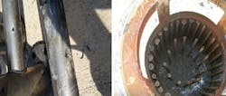
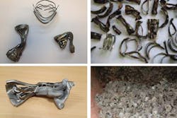
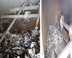
Figs. 2-5 compare photographs taken at South Pars 12 (left side) with nearly corresponding ones from the Society of Petroleum Engineers Technical Meeting (SPETM) addressing Bass Straits (right side). The systems exhibited similar clogging tendencies of holes in the distributors. Packing elements suffered extensive damage via twisting and crushing, requiring new packing. The burping force broke the upper section's packing through the wire mesh-type bed limiter at South Pars, while packing settled on the bed limiter in SPETM with relatively less damage (Fig. 5).
The major difference between the two cases is the materials deposited on the internals of the still column. All five operators in SPETM agreed that iron carbonate was the material deposited. Extensive testing of the South Pars events established that the material deposited was calcium carbonate (calcite). Both deposits appeared white in color (Fig. 4).
The frequency of filter element changes during the South Pars event was so high that operators ran out of filter elements and had to bypass the filters briefly, allowing unfiltered fluid to enter the column before shutting it down. This made the surface of the deposit appear to be blackish while the core was clearly white (Fig. 4).
The solids retained by the feed filters (Fig. 3) were blackish in color in both cases. Analysis of one sample in the South Pars case, however, revealed more than 90% calcium carbonate and 0.3% iron.
Corrosion, temperature
The most important environmental factors to understanding the differences in color and reasons for burping are the gas's corrosive component content, changes in temperature, pH, and ionic concentration of MEG solution as it moves through the loop. South Pars gas has about 3% carbon dioxide (CO2) and 0.8% hydrogen sulfide (H2S), compared with SPETM levels of about 0.9% and < 2 ppm, respectively.
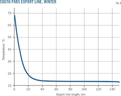
The South Pars export pipeline is about 150 km long with a 32-in. OD. It is laid in 70 m of water and the lowest sea bed temperature in winter is about 19.5° C. Fig. 6 shows the export line's temperature profile under winter design conditions calculated using standard software packages like OLGA.
At the entry point the temperature is high (73° C.) and decreases sharply within the first 25 km, steadily decreasing across the next 20 km to the near-seabed temperature of roughly 19° C. and remaining nearly the same for the rest of the pipeline's length. This trend would be similar in most operating long, multiphase gas condensate pipelines.
For convenience's sake we classify the initial 25 km of the line as the high-temperature zone (HTZ) and the last 70% of the line the low temperature zone (LTZ). HTZ reaction rates regarding both corrosion and bulk aqueous phase reactions are high when compared with LTZ. Bulk phase reactions in an MEG loop can occur when pH stabilization technique (PST) replaces corrosion inhibitors (CI) for corrosion control.
Under these conditions in HTZ, in the presence of formation water or stimulation products containing calcium (Ca), magnesium (Mg), barium (Ba), and strontium (Sr) chlorides, the alkali-methyl diethanolamine (MDEA), sodium carbonate (Na2CO3), etc.-added to stabilize the pH react with the chlorides and dissolved CO2, producing their respective carbonates. This is likely to continue in the bulk phase till the solution becomes acidic.
The bulk phase during this reaction normally becomes oversaturated with carbonates that tend to deposit as scales on the surface of the pipelines. For every 10° C. rise in temperature, the reaction rate is generally expected to double. HTZ is vulnerable to severe corrosion related damage and deposition of scales generated during bulk phase reactions.
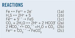
Bass Straits predominately used CI while South Pars used PST and CI both separately and in combination. South Pars used CI for corrosion control during burping. The various iterations of Reaction 1 and Reaction 2 represent expected surface events near the inner pipewall in the Bass Straits pipelines.
With H2S < 2 ppm both corrosion Reactions 1 and 2-iron reacting with H2S forming FeS and production of FeCO3 in reaction with CO2-occur. When H2S content in the gas phase at pipeline conditions crosses a threshold of 100 ppm, Reaction 1 predominates. The South Pars export lines therefore should not form iron carbonate. The lack of white precipitates in the MEG regenerator before mud return confirms that this is the case. The pre-mud return period also lacked burping and condensate carry.
Calcium carbonate returned with the remnants of lost mud is present in excess amounts in rich MEG during South Pars burping. The suspended solid particles travelling at a velocity of about 1 m/sec scour the surface of the FeS layer formed over the inner surface of the export line, resulting in significantly greater-than-normal amounts of iron in the rich MEG stream.
The FeCO3 reported in SPETM was generated in Reaction 2 mainly in HTZ and acts the same way as CaCO3 at South Pars, scouring the FeS layer and creating a high iron content in rich MEG. CaCO3 and FeCO3 solubility in MEG solution increases with decreasing temperature. When the slurry of CaCO3 or FeCO3-ridden MEG solution passes through LTZ more of these sparingly soluble salts go into the solution while the extent of dissolution is lower in HTZ. When water evaporates from such solutions in still columns at > 100° C, CaCO3-FeCO3 readily deposit on the column internals. Export line LTZ and evaporating temperatures in the still column therefore control movement and deposition of these soluble salts.
The solubility behavior of FeS under such conditions, however, is not well established. The absence of Fe in the deposits inside of the still column and its presence in sizable concentrations in the filtered solids before the still column in both the South Pars and Bass Straits cases remains unexplained. Discussion of problems faced by MEG loops in major North Sea and Gulf of Mexico gas projects highlights salt precipitations and consequences of CO2 corrosion, but lack the burping-type destructive events and presence of FeS or H2S.1
Discussion of FeS precipitation in the separator and oil carry-under of the topsides of a North Sea production site focused on formation water as the FeS source, attributing excess precipitation to the lowering of pressure from 60 to 18 barg due to liberation of dissolved CO2.8 These particles were very small (<1 μm) with a very large surface area.
Acknowledgment
The authors thank the management of Petropars Ltd and South Pars Gas Co. for allowing publication of this work. We thank SPE Victoria and Tasmania section for permitting use of the photographs presented at its technical meeting. The views expressed in this article are not necessarily those of our organizations.
References
1. Brustad, S., Loken, K.P., and Waalmann, J.G., "Hydrate Prevention using MEG instead of MeOH: Impact of experience from major Norwegian developments on technology selection for injection and recovery of MEG," Offshore Technology Conference, Houston, May 2-5, 2005.
2. Boschee, P., "Gas Hydrate Control Using Monoethylene Glycol in the Gulf of Mexico," Oil and Gas Facilities, Vol. 1, No. 3, June 2012, pp. 14-18.
3. Latta, T.M., Seiersten, M.E., and Bufton, S.A., "Flow Assurance Impacts on Lean/Rich MEG Circuit Chemistry and MEG Regenerator/Reclaimer Design," Offshore Technology Conference, Houston, May 6-9, 2013.
4. Flatten, E.M., Watterud, G., Andreassen, J.P., and Seiersten, M., "Precipitation of Iron and Calcium Carbonate in Pipelines at Varying MEG Contents," SPE International Oilfield Scale Conference, Aberdeen, May 28-29, 2008.
5. Baraka-Lokmane, S., Hurtevent, C., Ohanessian, J.L., Rousseau, G., Seiersten, M., and Deshmukh, S., "Prediction of Mineral Scaling in a MEG Loop System of a Gas Production Offshore," SPE International Oilfield Scale Conference, Aberdeen, May 30-31, 2012.
6. MEG Regeneration Technical Meeting, Society of Petroleum Engineers, Port Campbell, Australia, June 18, 2009.
7. Reynolds, R.M., "Physical oceanography of the Gulf, Strait of Hormuz, and the Gulf of Oman - Results from the Mt. Mitchell expedition," Marine Pollution Bulletin, Vol. 27, pp. 35-39, 1993.
8. Seiersten, M., Morland, B., Harvik, A.M.B., Istre, I., Rohde, H.C., and D. Vindenes, "Iron Sulphide Precipitation," Oil Field Chemistry Symposium, Geilo, Norway, Mar. 27-30, 2011.
The authors
D.R. Babu ([email protected]) is technical director at DHST Consultants, Bengaluru, India. He has served as contract and variations coordinator for South Pars (SP) 12 and SP 6, 7 and 8 projects at Petropars Ltd. and Iran Marine Industrial Co. (2003-2015). Babu also served as deputy chief consultant at Engineers India Ltd and as assistant general manager in Oil India Ltd. He has a BS in chemical engineering and obtained a PhD from Indian Institute of Science. He is a member of SPE and tech member of the Institution of Occupational Safety and Health.
Md. Hosseinzadeh ([email protected]) heads process engineering laboratories for SP 12 at Tombak, Iran. He was senior process engineer for operation and trouble shooting of various plants of SP 2 and 3. Hosseinzadeh earned BS and MS degrees in chemical engineering from Ferdosi Mashad University, Iran.
H. Akbary ([email protected]) is project director for SP 12 at Petropars Ltd., Tehran. He also served as engineering manager for SP 6, 7, and 8 and holds a faculty position at the Institute for International Energy Studies, Iran. Akbary holds a BS from Abadan Institute of Technology and a Ph.D from University of New Brunswick, Canada, specializing in fluid mechanics.
