New analytics, modeling improve subsalt drilling safety
Ruud Weijermars
Texas A&M University
College Station
Analytical models driven by advanced computing capacity and by numerical and physical models improve safety while drilling ultradeepwater subsalt basins. Subsalt deepwater drilling is complex even in the best conditions. When the salt canopy is unstable and mobile, complexity increases due to tectonic forces that jeopardize drilling safety and well integrity.
This article examines the mobile Sigsbee salt canopy in the deepwater Gulf of Mexico (GOM) and provides analytics and models that can be used safely to access the region's vast subsalt hydrocarbon resources. The literature referenced is reccomended for additional insights.
Sigsbee salt canopy
Paleogene sands of the GOM Wilcox formation are buried deep and hold massive volumes of hydrocarbons: 1.2 billion bbl of oil and 15 tcf of gas, according to early estimates.1
To reach the most prolific reservoirs, drillers must safely breach the thick Sigsbee salt canopy, a barrier that covers more than 137,000 sq km and is itself buried in overlaying rock of up to many kilometers in thickness.2
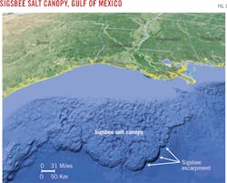
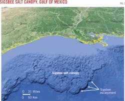
Continuing its crystalline creep towards the continental shelf, the mobile Sigsbee canopy is driven by coalescing salt sheets from more than 100 feeder stocks. The Sigsbee escarpment is the bathymetric expression of the leading edge of the expanding canopy (Fig. 1).
Finding a safe window for drilling through Sigsbee is complicated by the lack of pore space. Traditional fluid pressure can't be measured inside the salt body because free-fluids (other than occasional brine pockets) are absent. And balancing mud pressure in stable salt bodies is difficult, let alone in a mobile canopy.
Preventing wellbore closure
Sigsbee presents an additional problem: Any newly drilled hole can be deformed by the salt creep, which may close a wellbore before it can be completed.
How fast the open wellbore closes depends on three factors: The tectonic creep rate of the canopy, the local salt rheology, and the pressure differential between the hole and the ambient salt, which increases with depth.
Recent model studies quantify and simulate how the uncased wellbore may deform asymmetrically as it closes in such an environment.3 Well completion is a race against time to prevent asymmetric wellbore closures. When the completion job moves too slowly compared with the wellbore closure rate, costly complications may occur.
To prevent premature wellbore closure by salt creep, in-salt drill holes must be reamed and cased in a timely manner. Even these precautions offer no guarantee that the deforming force of salt creep on the wellbore has been stopped. While the creep can no longer directly close the cased wellbores, wellbore integrity may still be jeopardized because of the viscous drag exerted on the casing.
When the canopy salt layer becomes very thin and salt flow rates are high (which is often the case below sinking mini-basins nearing the base of salt in the canopy), drag forces can reach stress levels high enough to shear off the well casing at entry and exit points.4
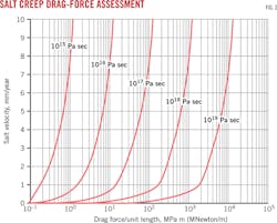
The drag force per unit length of standard borehole casing has been evaluated for a plausible range of salt viscosities (1015-1019 Pa sec) and assumes common salt creep rates of 0-10 mm/year. The resulting drag-force nomogram can be used for predrilling assessments of the drag force on cemented and steel-cased wellbores per unit-casing length (m) measured along the axial length of a drill hole embedded in mobile salt sheets (Fig. 2).
The drag force per unit length (Newtons/meter) is dimensionally equivalent to pressure times length (Pascals∙meter). The total drag over the vertical length of the salt section follows from the drag per unit length times the section of casing length exposed to creeping salt.
Synthetic flow maps
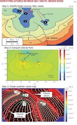
Another step for drilling safely through mobile salt is to identify contact zones (sutures) between individually fed salt sheets. Synthetic flow maps, which are generated by an analytical code that uses the locations of salt sources from seismic, can show where these zones occur.5 The code was developed with colleagues at the Applied Geodynamics Laboratory (AGL) at the Bureau of Economic Geology, University of Texas at Austin.
The flow speeds of the salt sheets issued from the feeder stocks can be constrained by dating the strata that are cut off by the advancing salt. These show up as ramps in the otherwise flat or gently sloping base of the salt.
The ramps act as timelines for the salt-spread rate. The model has been applied with data from the Walker Ridge region (Fig. 3).6 The likely location of suture zones between the advancing salt plumes can be identified even when otherwise invisible on seismic images from the salt's interior. Knowing where the suture zones are likely to occur mitigates drilling hazards.
Sediments from the roof of the salt canopy typically become trapped in sutures when the canopy forms.7 These trapped sedimentary blocks can either become over pressured or under pressured, both of which present difficulties for drilling.8
The over-pressured sediments may cause kicks and the under-pressured blocks may lead to a costly loss of drilling fluid and a sudden drop in well pressure. Sedimentary stringers trapped in suture zones may show up on enhanced 3D seismic images but are not always resolved.
The additional information from the new synthetic suture maps based on mathematical models of salt creep can help avoid drilling in the suture zones, especially when these zones are not recognized in seismic images of the salt body's interior.
Salt-tectonics models
Salt tectonics modeling has evolved. When AGL was founded in 1988, physical models of salt flow were initially made of opaque putty.9 With the emergence of computer modeling, the accuracy of physical models was questioned and analytical models were declared dead.
Today we have come full circle. Numerical models driven by advanced computing capacity are coupled with physical models that capture most aspects of the complex kinematics of mobile salt. Modern physical models use a transparent salt analog enabling advanced flow visualization, and scaling rules can translate the results back to the real world.10 11 Combined with analytical computer simulations, these models are applied to locate the systematic suture zones for the salt canopy in the Walker Ridge region (Fig. 3).5 6
With more ultradeepwater salt bodies recognized as mobile rather than stable (Angola, Brazil, Levant, and Pre-Caspian basins), the models and the steps outlined in this article will become increasingly important to ensure safe drilling.
Acknowledgments
The author thanks his colleagues Martin Jackson, Mike Hudec, and Tim Dooley for their contributions to the salt-tectonic research cited in this article. Arnaud van Harmelen is acknowledged for Matlab support.
References
1. Montgomery, S.L., Moore, D.C., "Subsalt Play, Gulf of Mexico: A Review," AAPG Bulletin, Vol. 81, No. 6, June 1997, pp. 871-896.
2. Hudec, M.R., Jackson, M.P.A., "The interaction between spreading salt canopies and their peripheral thrust systems," Journal of Structural Geology, Vol. 31, 2009, pp. 1114-1129.
3. Weijermars, R., Jackson, M.P.A., Van Harmelen, A., "Closure of open wellbores in creeping salt sheets," Geophysical Journal International, Vol. 196, No. 1, 2013, pp. 279-290.
4. Weijermars, R., Jackson, M.P.A., Dooley, T. P., "Quantifying drag on wellbore casings in moving salt sheets," Geophysical Journal International, Vol. 198, No. 2, 2014, pp. 965-97.
5. Weijermars, R., "Salt sheet coalescence in the Walker Ridge region (Gulf of Mexico): Insights from analog models," Tectonophysics, Vol. 640-641, 2015, pp. 39-52.
6. Weijermars, R., Van Harmelen, A., "Quantifying Velocity, Strain Rate and Stress Distribution in Coalescing Salt Sheets for Safer Drilling," Geophysical Journal International, Vol. 200, 2015, pp. 1483-1502.
7. Dooley, T. P., Hudec, M. R., Jackson, M. P. A., "The structure and evolution of sutures in allochthonous salt," AAPG Bulletin, Vol. 96, 2012, pp. 1045-1070.
8. Dusseault, M.B., Maury, V., Sanfilippo, F., Santarelli, F.J., "Drilling through salt: constitutive behavior and drilling strategies," presented to the 6th North America Rock Mechanics Symposium, Houston, June 5-9, 2004.
9. Weijermars, R., "Flow behavior and physical chemistry of Bouncing Putties and related polymers in view of tectonic laboratory applications," Tectonophysics, Vol. 124, 1986, pp. 325-358.
10. Weijermars, R., "Polydimethylsiloxane flow defined for experiments in fluid dynamics," Applied Physics Letters, Vol. 48, 1986, pp. 109-111.
11. Weijermars, R., Jackson, M.P.A., Vendeville, B., "Rheological and tectonic modelling of salt provinces," Tectonophysics, Vol. 217, 1993, pp. 143-174.
The author


