Custom offshore pipeline repair systems save money
Suzana Abilio
Stephane Taxy
Xavier Michel
Angola Deepwater Consortium
Luanda
| Based on presentation to Deep Offshore Technology International, Houston, Oct. 22-24, 2013. |
Establishing and operating a custom emergency pipeline-flowline repair system (PRS) for offshore deepwater projects can reduce repair times enough to justify the additional expense.
The Angola Deepwater Consortium (ADC) found that existing PRS concepts could be adapted with some qualification to cope with high pressure and the region's particular fluid characteristics and that these concepts could be further adapted to address pipe-in-pipe (PiP) repair.
The cost of a custom repair system covering 8- to 24-in. OD pipe might not be effective for a single operator, but sharing the system offers a much improved cost-benefit ratio.
Sonangol EP and Doris Engineering in 2000 formed ADC under the guidance of a joint industry project (JIP) steering committee composed of representatives from BP Angola, Cabinda Gulf Oil Co. Ltd. (CABGOC), ENI Angola, Esso Exploration Angola, Petrobras, and Total E&P Angola. ADC in 2009 began conceptual studies to screen and recommend appropriate technologies for an emergency PRS dedicated to Angola.
The PRS project included three phases:
1. Phase 1 demonstrated that creating a PRS club would reduce production downtime by having equipment ready for mobilization in Angola.
2. Phase 2 further investigated the benefits PRS could provide for Angola and in parallel defined the appropriate technical solutions to repair single-coated pipes through successive phases: conceptual, prefront-end engineering design (pre-FEED), and FEED.
3. The third phase began in April 2012, following the recommendations of Phase 2 to complete a PRS FEED document package, investigate PiP repair feasibility, and reach an agreement establishing a PRS club in Angola.
The PRS study covered uninsulated (water and gas injection), wet insulated, and pipe-in-pipe flowlines and pipelines. This article focuses on pipe-in-pipe repair feasibility via the diverless on-bottom spool repair method, cutting the pipeline and installing a spool using dedicated repair connectors.
Angola network
Since Angola's first deepwater developments in the late 1990s, its pipeline network has grown to 2,618 km (about 1,625 miles), with additional growth expected for several years. Analysis of JIP-collected data yielded the following details:
• Water depth, 20-2,200 m.
• Maximum design pressure, 555 bar.
• 1,524 km of 4-20 in. OD single-coated rigid pipeline installed or soon to be installed in water depths greater than 200 m.
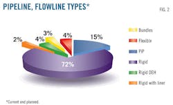
• 403 km of PiP lines installed or soon to be installed (representing 15% of all production lines).
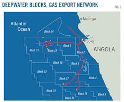
• An 836-km gas export network (Fig. 1).
The operators agreed not to consider bundles and flexibles but to focus the JIP on rigid and pipe-in-pipe technologies. These are the most common flowline types in Angolan deep waters.
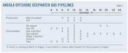
Table 1 provides the typical size of each pipeline type. Production duty centers on three main OD: 8, 10, and 12-in., with 6-in. included in the case of well jumpers. A wider variety of sizes makes up the gas export network.
Fig. 3 shows how much of each pipeline diameter each operator runs in Angola. Each color represents one oil company. The appearance of most companies across Fig. 3's spectrum suggests the synergies available jointly to address PRS. The JIP focused on 8-24 in. OD pipelines, which make up 94% of the lines off Angola.
Wet insulated flowlines
A conceptual study helped select the most suitable method for repairing wet insulated flowlines and any other single-coated pipe. The PRS's recommended approach centers on full-subsea, diverless deepwater repair, using one of two techniques:
• Integrity clamp. Repair with an integrity clamp will take place on minor localized damage provided the pipeline is not leaking when, for example, the flowline has been hit but not ruptured by a dropped object. This method reinforces pipeline structural integrity to prevent a leak caused by propagation of the damage.
• Repair with spool. Replacing the damaged section of the line on-bottom with a spool allows repair of major damage (e.g., rupture with leak). The repair spool can be either straight or shaped, depending on the characteristics of the section to be replaced. Before connector installation, a remotely operated vehicle (ROV) must prepare the sealing surface on the outside of the installed flowline to ensure a suitable surface for the seal.
Some operators have internal guidelines dictating that the spool-repair connection be vertical rather than horizontal. The JIP screened different repair methods considering both vertical and horizontal connections with various types of deepwater repair connectors.
Under considerations of cost and technical maturity, the PRS design's effect on installation vessel size and capability emerged as the main selection criterion. The presence of deepwater pipelines in Angola with OD greater than 20 in. required compromise on system design.
The JIP concluded that PRS design should be as compact as possible, with the combined ability to install either straight of shaped spools, so as not to limit the number of potential installation vessels. These concerns prompted the JIP to recommend horizontal orientation despite the practices of certain operators.
The JIP decided that repair operations should be performed with intervention vessels already typically available in Angola conducting routine inspection, maintenance, and repair (IMR). The minimum vessel required for an emergency pipeline repair would be a multipurpose vessel with a crane rated at 70 tonnes.
Characteristics specific to Angola affected PRS design, resulting in a gap between the available technology—primarily focused on post-hurricane pipeline repair in the Gulf of Mexico—and the technology that was required.
Water depth
The deepest producing Angolan field is at 2,100-m water depth (Block 31). But to ensure compatibility with possible future ultradeep water developments, PRS equipment should be qualified for use in water as deep as 3,000 m.
The JIP considered minimum water depths of 200 m, with repair of sections less than 200 m deep benefitting from diver assistance. Some PRS equipment, however, such as lifting frames, could support shallow-water repair operations to ease diver handling of large pipelines.
Soil data
Angola deepwater offshore soils consist mostly of very soft, highly plastic, clay. The JIP ensured that dedicated foundations can be developed to cope with these soils, which have a particularly low shear stress.
H-frames with foldable mudmats, and other PRS compact equipment, should remain within a 12-m × 8-m footprint to fit the deck of the IMR vessel. Potential ship-to-ship transfers in wave heights of 1.5 m suggest the need to keep the weight of such equipment lighter than 25 tonnes.
Qualification
Connectors for some Angolan flowlines have to withstand pressures exceeding 5,500 psi and sour service, again requiring development and qualification of repair components beyond what was previously available. The JIP is preparing a dedicated specification for connector qualification in accordance with industry standards such as DNV RP F113, API 6A, API 17D, and ISO 21329.
Thermal insulation
The repaired section of a production flowline is unlikely to meet design insulation specification for U-value and cooldown time. Insulation on the repaired section, however, must be sufficient not to compromise the operation of the flowline.
Pipe-in-pipe feasibility
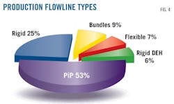
Fig. 2 showed rigid single-coated pipe to make up the majority of lines in the Angolan pipeline network. For production lines alone, however, PiP's proportion grows to 53%, with rigid single-coated lines dropping to 25%. The increasing use of pipe-in-pipe technology in Angola prompted ADC to conduct further investigation on their repairs.
Conceptual study
Repairing PiP lines requires restoring mechanical integrity while also guaranteeing insulation properties similar to the original. PiP damage includes flooding its annulus with seawater, which destroys the dry insulation material and exposes the annulus to corrosion.
Fig. 5 highlights the specifics of the two main categories of PiP technology: swaged J-lay and long continuous annulus.
• Swaged J-lay (Category A). PiP segment preparation typically occurs onshore. Deforming the outer pipe and welding it to the inner pipe seals the annulus at the end of each segment. Flooding thus affects one annulus compartment (in blue), while the other compartments remain watertight (in green).
• Long, continuous annulus (Category B). The annulus consists of long, continuous sections without compartments.
The JIP focused on repairing Category A PiP systems. Category B poses greater integrity issues stemming from the combined loss of thermal and mechanical integrity and the susceptibility to corrosion of the bare steel annulus.
Fig. 6 shows the JIP's recommended approach to restoring mechanical integrity for PiP Category B, using a combination of the connector for wet insulated flowlines with a newly developed annulus seal connector.
Insulation restoration
Thermal insulation in a Category B PiP system could typically be lost over 1-2 km in the event of a failure. PiP flowline design provides insulation with a U value of 0.5-2 w/sq m-K. If damage occurs, the annulus is flooded and its thermal properties are lost, allowing hydrates to form during cool down or shutdown before repairs can be executed.
The PiP insulation, combined with strict, precise operating procedures validated by extensive flow assurance engineering, makes restoring thermal integrity difficult. Degradation of the thermal insulation will most likely invalidate the system's standard operating procedures.
Re-evaluation of operating procedures based on degraded insulation would require emergency, labor intensive, re-running of flow assurance studies, including transient calculations. It would also create a number of practical issues regarding training of staff, managing the change, etc.
The JIP considered burying the PiP at a minimum depth of 1.5 m from its top among the options for restoring insulation of its flooded annulus. Though less than satisfactory for inspection purposes, burial with a trenching tool should provide the most efficient thermal insulation. Cool-down performance would be close to PiP initial specification.
Soil conductivity is a key parameter in thermal performance predictions. Burying the PiP at 1.5 m from its top in soil with 1.2 w/m-K conductivity yields a U value of about 4 w/sq m-K or lower.
Burying a pipe-in-pipe, however, is not sufficient to recover initial pipe-in-pipe insulation values. The operator must also modify field operating procedures (i.e. combined early depressurization and dead oil circulation).
Swaged J-Lay
The JIP sought to detail repair procedures further for Category A (swaged J-Lay), for which the loss of thermal insulation would be limited to a manageable length. No unsolvable problems were seen in applying on-bottom cut and repair to an insulated spool in a manner similar to that used for wet insulated flowlines. Repair would require development of a few additional tools, but neither feasibility nor qualification would be problematic.
Table 2 shows specifications of the dry-insulated PiP flowline used as the study's basis.
Repair objectives
When a Category A PiP is damaged, it results in at most 48 m of flooded section. Given this relatively short length, the optimum solution would be to replace the entire damaged section with an insulated spool, restoring original PiP insulation performance. This approach also solves corrosion issues, as long as cathodic protection and electrical continuity are installed for the tie-in section.
The line's mechanical integrity must also be restored. Connections between spool and PiP must be as resistant as any other section of the PiP to avoid weak points in the line.
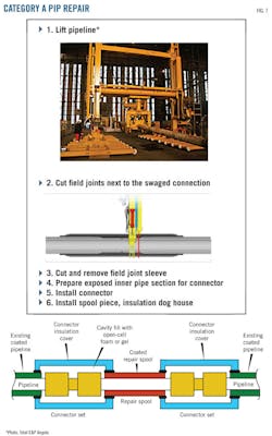
Fig. 7 shows the six steps of a typical swaged J-Lay (Category A) PiP pipe repair and its completed configuration.
Connector selection
The JIP considered two concepts for the repair connector. Fig. 8 shows the selected base case concept, which allows the use of the same connector technology already available in PRS equipment for the repair of wet insulated flowlines.
Once the damaged section of the pipe-in-pipe is cut, the now exposed inner pipe section can accommodate the connector. The operator must first cut the damaged section at the outer pipe swaged connection to avoid additional damage, relying on a compact cut-to-fit connector to join the spool and the inner pipe.
This concept seems realistic at feasibility stage, but a contingency case study may be necessary if the connector size increases during development. Cutting the damaged section upstream from the swaged connection and using the end preparation tool for removing the required outer pipe length in addition to the sleeve would provide the additional exposed length if needed.
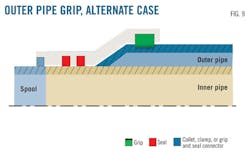
The JIP weighed the benefits of the base case connector against those of an alternative concept, which gripped the outer pipe instead of the inner pipe (Fig. 9).
The alternative's only benefit was the lack of restriction on the length of exposed inner pipe needed to accommodate the connector. It would, however, require the design and qualification of a new type of connector. Since the PRS study was attempting to standardize equipment between wet insulated flowlines and PiP flowlines, it chose the base case concept.
Repair operations would be similar to those executed on rigid pipe from IMR vessels, with only minor cost increases associated with adding equipment if planned sufficiently in advance.
Acknowledgment
ADC thanks the JIP participants, their steering committee members, and subject matter experts for their continued support and advice and for permission to publish this article. ADC also thanks AS Connector, Oceaneering, and Oil States Industries for their support.
The author
Suzana Abílio ([email protected]) is a project engineer at Sonangol EP, Luanda. She is attached to the subsea department, supervising installation of equipment and structures on the seabed and providing technical and economic analysis during subsea project approvals. She holds a BS (2009) in petroleum engineering from the University of Tulsa and an MS (2014) in energy and markets from the French Institute of Petroleum's IFP School, Rueil-Malmaison.
Stephane Taxy ([email protected]) is technical manager subsea and production at Doris Engineering with 17 years of experience in the oil and gas industry. He has worked as a process and flow assurance engineer developing numerous offshore deepwater oil and gas projects. Taxy currently manages projects for the Angolan Deepwater Consortium to share industrial approaches in Angola with deepwater operators.
Xavier Michel ([email protected]) is senior pipeline engineer at Doris Engineering with 11 years of experience in the oil and gas industry. He has been involved in the pipeline-flowline repair system project since its first phase and is now responsible for coordination of technical matters.
