Megat A. Rithauddeen
Shadi Al-Adel
Robin D. Tems
Saudi Aramco
Dhahran
Elemental sulfur in the produced gas from Hasbah gas field in the Arabian Gulf off Saudi Arabia raised concerns about flow assurance and corrosion. Saudi Aramco chose to inject a sulfur solvent into the gas production pipeline, the most common mitigation for sulfur deposition.
In such applications, the selected sulfur solvent must be compatible with other chemicals in the system including the corrosion inhibitor (CI) and monoethylene glycol (MEG), the latter chosen for hydrate inhibition.
This article discusses a chemical compatibility study performed to determine whether the presence of the sulfur solvent and the selected CI were reducing the effectiveness of the MEG hydrate inhibitor. This work involved evaluating mixtures of CI and the sulfur solvent at different concentrations with induction-time testing methods.
Sulfur solvent selection and efficiency were studied first, followed by the chemical compatibility study with MEG and the selected CI. The CI selection evaluation is not covered in this paper.
Habash field
Elemental sulfur dissolved in produced gas may precipitate in both the near-well reservoir region and tubing.1 This could reduce production by blocking the tubing.
In general, sulfur deposition poses problems for flow assurance and is a corrosion threat when the gas is wet. A catastrophic corrosion problem can occur when water and elemental sulfur are present inside a carbon steel pipeline.2 Large amounts of free water condense within the long trunkline, especially during winter.
In such situations, both hydrate inhibition and sulfur deposition mitigation must be applied.
The most efficient method to control blockage and corrosion problems caused by elemental sulfur is to inject a sulfur solvent with the CI,2 while the preferred choice for suppressing hydrates for long-distance pipelines is MEG as a thermodynamic inhibitor.3
Various studies have evaluated the compatibility between solvent and CI, but to the authors' knowledge none has looked into the effect of the sulfur solvent on the thermodynamic inhibitor performance.
When it is commissioned later this year, the gas processing plant in Wasit will receive Hasbah offshore gas. The plant is to produce 1,750 MMscfd of 1,080 btu/std. cu m equivalent sales gas and 4,200 tpd of sulfur (OGJ Online, Jan. 28, 2011). The gas is lean with no hydrocarbon condensate.
Water condenses throughout the pipeline, mainly due to the Joule-Thomson (J-T) effect, temperature drop being more severe during winter. Condensation of water within the pipeline prompts the need for effective corrosion and hydrate control measures.
One additional problem is the presence of elemental sulfur in Hasbah gas. Initial in-house gas sampling from Hasbah field had indicated the possible presence of elemental sulfur. Follow-up bottomhole samples were collected, conditioned, and shipped by Schlumberger to Alberta Sulphur Research Ltd. (ASRL), Calgary.
Preliminary analysis showed that the samples contained elemental sulfur as high as 5 lb/MMscf, which equates to about 6,500 lb/day of sulfur. The gas will be well undersaturated with elemental sulfur under reservoir conditions as the constructed equilibrium diagram suggests that the maximum gas solubility under the Hasbah reservoir conditions is greater than 150 lb/MMscf of sulfur.
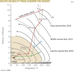
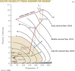
The analysis also determined sulfur deposition potential and impact on gas production and processing equipment. With elemental sulfur present as a dissolved species in the produced Hasbah sour gas, sulfur deposition can take place in the wellbore and surface equipment (Fig. 1).
Sulfur deposition depends heavily on pressure and temperature changes. The analysis indicated that the expected changes in pressure and temperature to be encountered by the produced gas from wellhead to onshore processing will result in retrograde sulfur condensation or precipitation and subsequent deposition during production. The effect of this deposition includes wet sulfur corrosion or periodic production interruptions due to plugging.
Chemical inhibition to address the corrosion, hydrate concerns, and elemental sulfur deposition was considered.
Corrosion control of the carbon steel wet-gas pipelines will be achieved by use of internal coating in conjunction with batched corrosion inhibitor (BCI) and a CI. Primary hydrate control will be by MEG. An MEG injection system is planned to transport MEG and CI continuously from the treatment plant ashore to each tie-in platform (TP) and wellhead platform (WHP). MEG will be circulated continuously together with the CI between the glycol regeneration units in the gas plant and the TPs and WHPs.
The most common way to remove sulfur, and thereby resolve the sulfur deposition, is by injecting sulfur solvent. Two types of sulfur solvent were considered: physical and chemical.2
Rigorous and extensive tests were conducted to determine the appropriate sulfur solvent. Subsequently, a detailed chemical compatibility test protocol determined the most suitable CI in the presence of the sulfur solvent. In addition, tests determined if these chemicals would reduce the hydrate thermodynamic inhibitor's performance.
Various vendors submitted continuous corrosion inhibitors to be evaluated for the project to meet defined performance requirements. Generally, these were water soluble and dispersible organic chemical formulations dissolved in organic solvents. Formulations were proprietary to each vendor but generally included a blend of amines and other components.
The first part of the tests was conducted by Alberta Sulfur Research Ltd. laboratory in Calgary. The compatibility tests were conducted at the Institute for Energy Technology in Norway.
Solvent screening
The available treatment option for gas well sulfur plugging is solvent injection. The most common type of treatment is with a once-through application in which the chemical is recovered with the well liquids but not reused.
Regenerable solvent techniques are available, but few companies seem to employ them. In particular, Mobil Erdgas-Erdoel GmbH in northern Germany uses alkylnaphthelene and a mineral carrier oil with boiling ranges of 240-270° C. Crystatech is developing a new regenerable solvent technique. These techniques seem to be generally for downhole injection.4
Regenerable processes were not considered at this stage for this offshore application because they are expensive and involve additional solvent separation and control at the plant to enable resue offshore. Furthermore, they require onshore regeneration equipment, such as solvent surge vessels, crystallization and filtration equipment, and pumps and subsea lines from and to the plant ashore. This is similar to the MEG regeneration system.
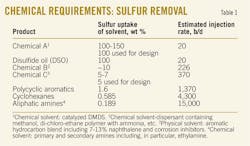
A comprehensive study identified the potential sulfur solvent for Hasbah field application. Table 1 represents information provided by ASRL and sulfur solvent suppliers about sulfur uptakes and estimated injection rates for several proposed solvents. This information is based on sulfur uptakes at the lowest possible operating temperature of 44° F., and injection rates are calculated for 5 lb/MMscf sulfur. The lowest temperature was chosen to represent the worst-case scenario, as the sulfur decrease is lower at lower temperatures.
The numbers presented in Table 1 are based on pure chemical data and should be treated as guidelines only. Actual uptake capacity of commercial solvents depends on the solvent formulation and operating conditions. Fit-for-purpose tests are recommended once solvent suppliers are identified to determine accurate injection rates as well as system compatibilities.
Based on the preliminary findings and on ASRL recommendations, Saudi Aramco decided to limit the solvent selection to hydrocarbon-based solvents from different local refinery cuts that are known to contain polycyclic aromatics.
Different grades of Arab crude oil (Light, Medium, and Heavy) were tested at the laboratory as potential sulfur solvents. Initial sulfur uptake testing of Arab Light, Medium, and Heavy crude oils revealed that, at the temperatures examined, Arab Medium crude oil has a sulfur uptake capacity about one half when compared with light cycle oil (LCO) and heavy diesel oil (HDO). Although this option looked promising, it was later dropped because the miscibility studies indicated that under test conditions, virgin crude oil will form stable emulsions with MEG, and sulfur saturated crude oil will form stable emulsions with H2O and H2O/MEG (60:40 by volume) at T = 20° C.
Due to availability, technical concerns, and logistical reasons associated with other evaluated solvents, HDO from a local refinery in the eastern region (close to Wasit gas plant) was chosen for the sulfur solvent for Hasbah gas. Based on sulfur uptake capacity of 0.7 wt %, a flow rate of about 3,800 standard b/d of HDO will be required. Accordingly, solvent delivery and handling systems were developed based on trucking and storing fresh HDO solvent at the plant.
A chemical compatibility study involved two objectives:
1. To qualify a CI that meets the corrosion allowance criterion and is compatible with all other chemicals within the system. In addition, the CI should be able to survive the MEG regeneration system to reduce chemical make-up cost sharply.
2. To evaluate the impact of corrosion inhibitor on the performance of MEG as a hydrate inhibitor for Hasbah conditions. Any detrimental effect of the addition of corrosion inhibitor or HDO should be identified.
The remainder of this article will focus on the second part of the compatibility test and briefly explain the corrosion inhibitor test findings.
MEG studies
Extensive studies of MEG performance show that the effect of MEG is predictable.3 5 6 Its effect on the depression of the formation pressure and temperature is similar, regardless of the type of hydrate and hydrate-forming species. This means that the presence of MEG will inhibit all types of hydrates.
No species detrimental to the inhibiting properties of MEG appear in the literature. Corrosion inhibitors are typically added to the lean MEG stream during continuous injection. This means that corrosion inhibitors or HDO are not expected to affect in any major way the hydrate equilibrium temperatures obtained with MEG as inhibitor. It should also be noted that the concentration of thermodynamic inhibitors such as MEG is very high (typically 40-60 wt %).
This means that the effect of impurities on MEG will be negligible until a high concentration is reached. No evidence of any effect of corrosion inhibitor molecules appears in the literature.
Some of the low-dose hydrate inhibitor (LDHI) structures have active groups and solution properties similar to corrosion inhibitors. These inhibitor structures are sometimes used in conjunction with MEG, indicating no detrimental effect of combining MEG and a surfactant.7
No reported data indicate the presence of water-soluble corrosion inhibitors has a detrimental effect on the thermodynamic inhibitor efficiency. Detrimental effects have been reported in the use of LDHI, and not thermodynamic inhibitors, in conjunction with corrosion inhibitors.
A large amount of field data on MEG or a combination of MEG and a low-dose hydrate inhibitor for hydrate control has been published.3 7-9 The results show that hydrate control can be achieved with both thermodynamic inhibitors and LDHI or a combination of these.
In several of the fields in which thermodynamic inhibitors are used (MEG or MeOH), corrosion inhibitors have been successful alongside thermodynamic inhibitors.10 11 The corrosion inhibitors are usually injected through the lean MEG injection pipeline in these systems because the inhibitors are water-MEG soluble.
No data were found regarding the injection of oil-soluble inhibitors and their effect on MEG performance. It is apparent that corrosion inhibitors might increase the hydrate formation potential because they are water dispersible (not soluble).
A water-dispersible product is one that results in the oil-soluble species of the CI existing in the water phase, typically as a homogeneous suspension or fine reverse emulsion of the CI components, brought about by the appropriately designed surfactant package of the CI. A conservative approach must therefore evaluate if additional hydrocarbons might be dragged into the aqueous phase.
Hydrocarbons might therefore be dragged into the aqueous phase through the formation of emulsions. This effect increases the hydrate formation kinetics by increasing the water-to-gas (hydrate forming molecules) contact area. No effect on the thermodynamics of hydrate formation-in terms of the hydrate equilibrium line-in the presence of MEG is expected.
The literature findings for MEG performance are consistent with the laboratory tests conducted.
Hydrate tests
The hydrate tests were carried out in an RC5 rocking cell hydrate testing instrument from PSL Systemtechnik. The instrument was equipped with five Hastelloy cells designed to handle sour service. For each run, four cells were used for testing of the desired conditions and one cell was used as reference (baseline) without corrosion inhibitor.
The reference cell was included to detect and compensate for small variations in the gas composition (that is, if thereby a mistake was a slight deviation of the gas filling it would also cause a small shift of the hydrate melt temperature for the reference cell). This was done to ensure that evaluation of the results was measured against a blank test, which revealed the relative effect of the added chemicals.
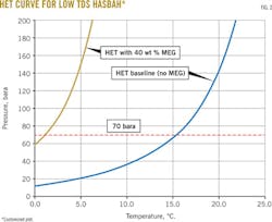
Theoretical hydrate equilibrium (HET) was calculated with PVTsim, a common software used for hydrate simulation. The theoretical data were compared with the experimental data for each condition tested. Fig. 2 shows the HET experimental data.
Pressure, temperature results
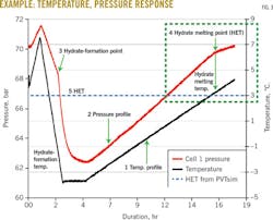
Because interpretation of the pressure and temperature graphs can be complicated, the following is a detailed explanation. As shown in the example in Fig. 3, each chart contains at least two curves:
• Temperature as a function of exposure time (always black, just one curve).
• Pressure as a function of exposure time (up to five curves, each with a different color).
All curves use the same time scale.
The important sections of the chart, labeled 1 through 5, show the following features:
1. Temperature recording.
2. Pressure recording.
3. Breakpoint indicating the initial hydrate formation during cooling.
4. Breakpoint indicating melting of the last hydrate during heating.
5. The hydrate equilibrium temperature as estimated by PVTsim.
From Point 3 (hydrate formation) and Point 4 (hydrate melting) on the pressure curve, the HET can be found by reading the temperature at the same time of the test. This is shown by vertical arrows from the pressure graph to the temperature graph.
The data show that there was a large discrepancy between the hydrate formation and hydrate melting temperatures. During solution cooling, no hydrate will form immediately after the temperature has crossed the (ideal) HET. Fig. 3 shows where no hydrate formation is observed until the temperature has reached about -3° C.
The delay in hydrate formation during cooling is a kinetic effect, in which a certain subcooling and time are needed for hydrate to form. If a slower cooling had been used, the hydrate formation point would be much closer to the HET found with PVTsim. In the present work, the hydrate melting point (Point 4) was used to find HET during slow heating.
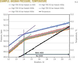
Note that only the interesting part of the pressure-temperature curves, the hydrate melting point, is reported here and shown in Table 2 and Fig. 4.
The results in Table 2 show that the temperature difference-between hydrate formation for the reference test (no inhibitor) and the test with continuous inhibitors only-is less than 0.5° C. When batch inhibitors are added at a concentration of 2 wt %, the results indicate that the melting temperature decreases by 0-1.5° C. As mentioned previously, a decrease in melting temperature means that the stability of the hydrate decreases.
No indication of an increase in the melting temperature is observed in the presence of BCI. There are small deviations in the reference temperature results.
This deviation in the recorded reference temperature is most likely due to small inaccuracies in the partial pressures of the individual gas components. The deviation has no effect on the relative comparison of results with and without the corrosion inhibitor.
The results confirm that the presence of tested CI and BCI products did not reduce the hydrate inhibition performance of MEG at the conditions tested (i.e., these chemicals do not increase the hydrate formation temperature). Slight scattering in the melting temperature is most likely related to small variations in the gas composition and total pressure at the HET. There was no indication of an increase of the melting temperature in the presence of the batch corrosion inhibitor.
As shown in Table 2 and Fig. 4, the presence of HDO had no effect on the hydrate inhibition performance of MEG. This accords with the findings in the literature review.
Corrosion tests
The primary concern of corrosion inhibitor testing was to evaluate each inhibitor's ability to control pitting in addition to general corrosion in the production environment. Both CIs and BCIs were evaluated.
In accordance with the field design, CIs are delivered to the field through the recirculating MEG hydrate control system. Part of the evaluation was to consider aspects related to deliverability and reprocessing of the CI that travels along with the MEG.
The test program evaluated the partitioning of the CI between the aqueous MEG phase and the hydrocarbon sulfur solvent phase. And the program evaluated emulsion formation and foaming.
Further, it evaluated the ability of the CI to survive and inhibit corrosion after reprocessing through the MEG plant. A portion of the MEG flow through the plant (about 37%) is routed through a reclaimer that will destroy the CI. The rest of the CI is to survive reprocessing and be recirculated to the field.
An autoclave test program evaluated the corrosion control effectiveness of the CIs, designed to simulate the range of corrosive environments encountered. Weight loss corrosion was measured and electrochemical linear polarization resistance (LPR) measurements were made. Pitting corrosion was determined by surface scanning with a 3D profilometer with white-light axial chromatism.
Additional tests measured "shut-in persistency," simulating a stop in production with treated fluids in place, and "flowing persistency," simulating a loss of corrosion inhibitor feed to the MEG system during normal production.
Saudi Aramco's corrosion management program requires a BCI treatment program to minimize top of the pipeline corrosion and to reduce solids arriving ashore in the MEG reprocessing system.
BCIs were evaluated with two different techniques: a conventional "dip and drip" method followed by autoclave exposure and a novel top-of-the-line corrosion cell designed specifically to simulate application of the batch inhibitor via a spray-jet pipeline pig. The effect of solid deposition was also studied in the dip and drip series of experiments.
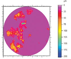
All corrosion inhibitors tested reduced general mass loss to less than 4 mils/year (mpy; 0.1 mm/year). Not all products were successful in controlling localized corrosion. Successful products reduced the pitting corrosion rate to less than 15 mpy, the detection limit of the experiments.
No pitting was visible. Some CIs caused increased levels of pitting with pitting rates about equivalent to 300 mpy in the presence of the corrosion inhibitor. Extensive localized corrosion was visible (Fig. 5).
New territory
By producing from its offshore sour lean gas fields, Saudi Aramco has entered a new territory of gas production. In the first offshore gas field, Karan, qualifying kinetic hydrate inhibitors compatible with corrosion inhibitors for sour lean gas was successful. This article discusses mitigating sulfur deposition, controlling corrosion, and inhibiting hydrates simultaneously for Hasbah gas field. A series of comprehensive tests yielded a better understanding of the interactions between sulfur solvents, corrosion, and hydrate inhibitors.
The results of those tests enabled Saudi Aramco to identify specific chemicals to meet the sulfur deposition mitigation and corrosion inhibition for Hasbah offshore gas field that will be treated at the Wasit gas plant. Subsequently, the chemical compatibility tests provided the opportunity for Saudi Aramco to determine whether any of these chemicals would adversely affect MEG performance, from a hydrate inhibition perspective and vice versa.
Interactions between the corrosion inhibitors, reprocessing through the MEG regeneration plant, and the other field treatments have been examined and corrosion inhibitors that formed deposits, foams, and emulsions or did not satisfactorily inhibit corrosion have been rejected. This means that the qualified CI that will be blended with MEG-which will be recovered ashore and reused-does not deteriorate when passing through the MEG regeneration plant. Consequently, this will improve the chemical consumption operating expenditure in the long run.
In addition, the optimum dose rate required to mitigate corrosion and inhibit hydrate can be determined. As a result, the MEG injection system and regeneration system design for the Wasit gas plant can be further optimized in the future.
Acknowledgements
For their support and assistance in providing data related to hydrate inhibition and corrosion mitigation, the authors thank various people within Saudi Aramco in the process and control system department and the consultancy services department involved in the sulfur solubility tests and MEG/CI/HDO compatibility program. In addition, the authors appreciate the contributions of Alberta Sulfur Research Ltd. and the Institute for Energy Technology by providing the laboratory data used in this work. The authors recognize the contributions of SAIPEM and Saudi Aramco's project management team.
References
1. Tang T., Voelker J., Keskin C., Xu Z., Hu B., and Jia C., "A Flow Assurance Study on Elemental Sulfur Deposition in Sour Gas Wells," SPE Annual Technical Conference and Exhibition, Oct. 30-Nov. 2, 2011, Denver.
2. Sun, H., Fang, H., Davis, J., and Hudgins, R., "Elemental Sulfur Corrosion and Inhibition in the Presence of Solvent," NACE International Corrosion 2011 Conference and Expo, Mar. 13-17, 2011, Houston.
3. Brustad, S., Løken, K.-P., and Waalmann, J.G., "Hydrate Prevention using MEG instead of MeOH: Impact of experience from major Norwegian developments on technology selection for injection and recovery of MEG," Offshore Technology Conference, May 2-5, 2005, Houston.
4. Rameshni, M., "Elemental Sulphur Deposition Mitigation Evaluation for Offshore Natural Gas Reservoir," www.rate-engr.com/documents/offshore%20sulphur%20deposition%20mitigation.pdf.
5. Carroll, J., Natural Gas Hydrates-A Guide for Engineers, Amsterdam: Elsevier BV, 2009.
6. Chapoy, A., Anderson, R., and Tohidi, B., "Low-Pressure Molecular Hydrogen Storage in Semiclathrate Hydrates of Quaternary Ammonium Compounds," Journal of the American Chemical Society, Jan. 6, 2007, pp 746-747.
7. Szymczak, S., et al., "Chemical Compromise: A Thermodynamic and Low-Dose Hydrate-Inhibitor Solution for Hydrate Control in the Gulf of Mexico," SPE Annual Technical Conference and Exhibition, Oct. 9-12, 2005, Dallas.
8. Elhady, A.A.A., "Operating Experiences of DEG and MEG for Hydrate and Dew Point Control in Gas Production Offshore Mediterranean," International Petroleum Technology Conference, Nov. 21-23, 2005, Doha.
9. Budd, D., et al., "Enhanced Hydrate Inhibition in Alberta Gas Field," SPE Annual Technical Conference and Exhibition, Sept. 26-29, 2004, Houston.
10. Bonis, M., "Sour Weight Loss Corrosion Management: An Extensive Review of Present Field Experience," International Petroleum Technology Conference, Dec. 7-9, 2009, Doha.
11. Tobiassen, P., and Pedersen, A.E., "Experience Feedback On The Use Of A Carbon Steel Subsea Pipeline For A High Pressure, Sweet Service Gas Field," Corrosion 2004, Mar. 28-Apr. 1, 2004, New Orleans.
Based on a presentation to 22nd Annual Technical Conference of the Gas Processors Association-Gulf Cooperation Council Chapter, May 13-14, al Manama, Bahrain
The authors
Megat Ahmad Rithauddeen([email protected]) is a senior process engineer for Saudi Aramco, currently part of the upstream process engineering division. He also leads the hydrate inhibition management program. Before joining Saudi Aramco in 2011, he was a process specialist in the process optimization engineering unit in RasGas Ltd., Qatar, and has more than 15 years of experience in the oil and gas industry in the Middle East and Malaysia. Megat holds a chemical engineering (with honors) degree from Monash University, Melbourne, Australia, is a chartered engineer, and is a member of the Institution of Chemical Engineers.
Shadi Al-Adel ([email protected]) is a process engineer for Saudi Aramco, currently heading the gas processing unit in the process and control systems department and the technical committee chairman of the GPA-Gulf Cooperation Council chapter. In 2013, he completed his internship in process engineering design with WorleyParsons in California and led the hydrate inhibition management program for Saudi Aramco's offshore gas projects during 2009-11. During 2007-08, he worked on the commissioning and start-up of the largest NGL recovery plant within Saudi Aramco, Hawiyah NGL recovery plant. Al-Adel holds a BS (2000) in chemical engineering from King Fahd University of Petroleum and Minerals and an MS (2007) in chemical from McGill University.
Robin D. Tems([email protected]) is the corrosion and materials senior engineering consultant in the consulting services department, capital projects support group of Saudi Aramco. Before joining Saudi Aramco, he was a corrosion expert at Mobil Research and Development and Mobil Exploration Norway. Tems chairs the NACE STG-08, Corrosion Management; is an International Professional Engineer, Chartered Engineer, and Chartered Scientist; and holds a PhD in engineering from Newcastle University, UK.
