Systematic approach streamlines natgas pipeline pressure increase
| Based on presentation to Pipeline Technology Conference, Hannover, Germany, Mar. 18–20, 2013. |
Ales Brynych
CEPS AS
Belnicka, Czech Republic
A sequence consisting of internal inspection, elimination of major defects, and subsequent pressure testing is the most efficient way to ensure the integrity and increase the operating pressure of aging high–pressure natural gas transmission pipelines.
Gas flow through Polish pipeline systems has been gradually changing to west–to–east from east–to–west, the direction it's flowed in the last few years. This transition has led to a requirement to increase the capacity of gas pipelines to transport gas at 7.4 MPa (1,073.28 psia) in some Polish regions. This increase is achieved not only by building new high–pressure pipelines but also by integrating older revalidated pipelines operated in the past at lower pressures.
An example of this comprehensive approach was revalidation of the 55–km (34–mile) gas pipeline DN 400 in southwestern Poland. Revalidation included the following steps:
• Cleaning the pipeline.
• Performing inline MFL inspection.
• Material testing of samples taken from the original pipeline.
• Model integrity testing of pipe body vessel taken from the original pipeline.
• Designing working procedures for integrity test.
• Preparing the pipeline for testing.
• Integrity testing, drying by super dry air.
• Final reporting.
Basic data
Pipeline DN 400, with a nominal operating pressure of 6.3 MPa, mainly supplied the area around Jelenia Gora with natural gas. It was as built in 1991–92 and 1997 from helical welded pipes with 406–mm (16–in.) OD and 6.3–mm WT 18G2A steel. Pipe bends into protective pipes and crossings used 406 x 8.8–mm R45 pipes. Only partial documentation of the original post–construction testing remains for the 18G2A sections, and none for R45.
Pipeline design and construction included cleanability, with entry and exit traps included for launching and receiving cleaning pigs. DN 400 has three branch pipelines: DN 250, 150, and 100.
Cleaning, inspection
T.D. Williamson Polska performed the first phase of cleaning and inspection. The operator said the pipeline had never been cleaned while in operation and probably not even during construction. Despite the considerable risk of the pig becoming stuck either by impurities or deformed pipe, the operator required cleaning to occur without the pipeline being shut down.
During the first pass the cleaning pig stuck about 40 km down–pipe near a railway crossing. Excavation found a sharp vertical segment bend, which hindered pig passage. After removal of this segment, the pipeline was cleared for cleaning pigs. The second cleaning pig made it to the receiving trap and several additional cleaning runs followed. The first successful run alone half–filled the cleaning trap at the end of the line with dust.
Post–cleaning internal inspection used calibration and magnetic flux leakage (MFL) tools. The MFL tool detected many loss–of–wall fitness defects, the most severe measuring up to 79%. After shutdown of the pipeline from operation (but before start of integrity testing), TDW dug up the largest defects and, depending on severity, either cut them out or covered them with a sleeve.
Material tests
While cutting out an unsatisfactory segment bend, TDW also removed a sample of the 406 x 6.3 mm pipe for testing. This pipe section provided samples for material tests, with another 3–m length turned into a pressure vessel for burst tests. Existing inspection reported these as helical–welded 406 x 6.3 mm 18G2A steel pipes, with a guaranteed minimum yield strength of 350 MPa.
Test results showed the steel to be a low–carbon type CSN 41 1523, St 53 in accordance with DIN 17172, or X52 according to API Spec 5L. Table 1 provides the results of chemical analysis.
Tensile tests used flat bars, one each taken from the longitudinal and circumferential directions of the pipe. Table 2 supplies tensile test results. Comparison with the mechanical characteristics required for steel L 360 NB (MB) according to CSN EN 10208–2 yielded satisfactory values.
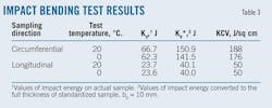
Impact bending tests also used samples collected from the circumferential and longitudinal directions of the pipe (Table 3). The values of impact energy KV* in circumferential direction between 20° C. and 0° C. are favorable, above 140 J. The values obtained on samples taken in the longitudinal direction at both temperatures were less favorable at 40 J. Longitudinal results do not meet standard requirements of CSN EN 10208–2, an average KV* value of 60 J.
Metallographic analysis again used cut–outs from the longitudinal and circumferential pipe directions. Sulfide presence was favorable, occurring only on the pipe surface. Any inclusions on the surface were of good to average quality.
The steel had a fine–grained ferritic–pearlitic structure, ferrite grain size corresponding to No. 8.5–7 in the relevant standard. Its structure, however, was not linear, pearlite lines occurring sporadically in an otherwise polyhedrosic make up. Pearlite excretes in lamellar form, with chains of tertiary cementite sometimes excreted along with the ferritic grains. Pipe surfaces did not show decarburization.
Testing determined the pipe's helical weld to be of good quality. The line and vertical rise on the outer surface were satisfactory. The inner surface rise was satisfactory, even though the line was not ideal. Weld structure showed a columnar character consisting of ferrite–pearlite.
Overall, testing classified the mechanical and structural quality of the steel as standard, without major defects.
Vessel testing
Material testing results helped determine pressure values for integrity testing of the test–pipe vessel. The 406 x 8.8 mm R45 steel pipes had a manufacturer–guaranteed minimum yield strength, Remin, of 255 MPa. The lower yield strength compensated for the greater WT, making the pressure value of the material–tested 406 x 6.3 mm and 406 x 8.8 mm pipes identical. The operator did not provide samples of the R45 steel pipe for testing.
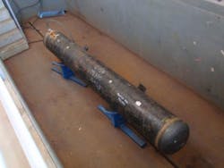
The test pipe vessel (Fig. 1) measured 2.9 m long with a volume of 360 l. It was closed on both ends and fitted with nipples. Testing gradually pressurized the vessel to yield strength, a value of permanent integral circumferential deformation of ε 0.05%, and then to destruction. Table 4 summarizes values achieved during pressurization.
Integrity tests included online monitoring and measuring of dependent variables p–V and p–t, the flow rate of water pumped in, total volume pumped in, size of pumped plastic volume, and value of the permanent integral deformation, ε.
Pressurization to 16,632 MPa destroyed the test vessel at its circumferential weld (Fig. 2).
Progress and results of performed vessels tests set maximum pressure, Pmax, for integrity testing, but with the maximum value of permanent circumferential deformation, ε, not exceeding 0.05%.
Integrity test
Division of pipeline DN 400 into four working units occurred before shutdown, with each unit then repaired in sequence before removal of defects, integrity testing and drying, and return to operation. Integrity tests took place on working sections of each working unit.
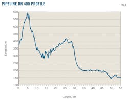
Division of the gas pipeline into working sections proved extremely difficult, the territory through which the pipeline travels more resembling the Bohemian–Moravian highlands or foothills of the Giant Mountains than the Polish plain. Fig. 3 shows the pipeline's longitudinal profile, elevation ranging from 100 to 600 m over its 55 km.
The operator required that the project be completed in 4 months or less, including:
• Division into four working units, with a resulting large number of disconnections, reconnections, and interconnections on live pipe.
• Cut–out or repairs of defects detected during internal inspection.
• Sourcing water for pipefill and subsequently disposing of the used water.
• Integrity testing.
• Drying.
Work occurred without interruption for weekends or holidays, with tests performed on 16 working sections. This number was a compromise between requests by an investor and the operator to minimize costs and contractor requirements that a representative sample be addressed.
No rules or standards govern integrity testing in Poland, leading the project to develop the implementation working process (RPP), which combined results from two separate processes. Strength tests, the main part of integrity testing, applied standard technological procedure S05 CEPS "Carrying out of pressure reparation and pressure test in accordance with Inspection Report ITI No. 706/02.05/06/15.07/1 dated 3.3 2006." Subsequent evaluation of tightness used Polish Code for carrying out stress tests and subsequent pressure tests of new pipelines, ZN–G–3900 "Proby specjalne." Both the operator and Poland's Office of Technical Inspection (UDT) approved the RPP.
Integrity test monitoring of dependence p–V and p–t occurred online and continuously, as did measuring the flow of pumped in water, pumped in total volume, size of the pumped in plastic volume, and value of permanent integral deformation, ε, which Proby specjalne does not require. The segmented implementation of the expansion and use of the chosen measurement protocols were recommended for future use on similar projects.
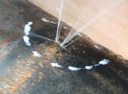
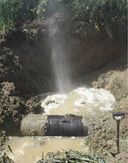
Integrity testing twice resulted in destruction of the pipe. The first was on a segment of pipeline built in 1997. During a time delay after reaching maximum pressure in the first pressure cycle, a significant drop in pressure occurred. Results of the first cycle of integrity testing and theoretical calculations estimated a 411–l./hr leak. This relatively large water leak was favorably situated, the defect on the upper part of the pipeline in relatively dry terrain was found during a walk of the line. A thorough moistening of the terrain in the area of the defect and repeated pressurization and subsequent spontaneous depressurization of the gas pipeline allowed the exact location of the leak to be found (Fig. 4).
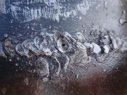
The site revealed a sloppy circumferential weld (Fig. 5). The welder did not spare any material in completing a weld that was perforated at its root. It is surprising that this weld passed initial inspection (B2, according to Czech standard TPG 702 04) carried out during construction of the pipeline in 1997. By comparison, construction of B2 pipeline DN 1000 from Lanžhot towards Mount St. Catherine, Czech Republic, built in the same period, subjected all circumferential welds to radiography tests, among other inspections.
Technicians immediately re–examined ILI inspection results, but no anomalies were found in the MFL tool's record, confirming CEPS's experience in internal inspection of more than 400 km of gas and product pipeline that intelligent MFL pigs are unable to detect pipeline defects of this type and scope.
The second leak occurred in a section built in 1991–92. During integrity testing, pressure fell 2.7 bar during 24 hr. A water leak of less than 6 l./hr caused this pressure drop. The 4.6–km pipe section ran from water–soaked forests into a field. The operator requested this section be divided into three sub–sections, which were repressurized to the pressure of the tightness test. Two sections were tight, while the third leaked 2.5 l./hr. Leak size regularly shrinks after division of the tested section into subsections.
Such small leaks in the pipe wall at high pressures are almost undetectable by the human eye. Frequently during dewatering and refilling, as the high–seal pig passes through the leaky section of pipe, it will clog or block any openings with particles of rust or sludge. On another leaky section the operator again requested it be divided into three subsections. No leak appeared during tightness testing. The defect was probably either clogged with dirt or had been inadvertently cut out while cutting the pipe into subsections.
The pipeline is secure after properly performed integrity tests. Once operational, however, the operator should inspect any referred sections with increased scrutiny, frequent patrols along the pipeline with a gas leak detector, and detection of faults in isolation by the Pearson method.
Pipeline drying
After integrity tests and reconnecting the working sections to one another, technicians dried the pipeline to –20° C., the dew point temperature (TRB) of water in the air leaving the pipeline. A mobile drying unit pushed super–dry air (TRB –80° C.) through the pipeline at 1,200 cu m/hr to dry it.
Bidirectional–disc cleaning pigs, followed by foam pigs, both pushed through the pipe by the super–dry air, removed remaining water from the pipeline during drying. The last foam pig entered the pipeline at –20° C. TRB. Technicians flushed the entire pipe one more time with –80° C. TRB air and then turned it over to the operator.
The author
Ales Brynych (ales.brynych@ceps–as.cz) is executive director of CEPS AS. He previously worked as director of production at CEPS and before that as chief technologist for three different companies. Brynych holds a BS (1993) in chemical processing of fuels and energy from the Institute of Chemical Technology, Prague.


