Water-injection testing improves terminal operations
Mohammad Zahedi
Azad University of Research & Science
Tehran
Kourosh Tahmasbi Nowtarki
Pars Drill Fluid Co.
Tehran
Research at Iran's Khark crude terminal shows the water-injection proving test to be the best evaluation method for determining the accuracy of crude and condensate sampling systems and suggests its inclusion in site-acceptance testing.
An autosampler extracts a representative sample from the liquid flowing through a pipeline. The sampler consists of several parts including a programmer to enable a representative sample to be obtained. The sampling result plays an important role in financial calculations. The most typical samplers in the oil industry are in-line, fast loop, and jet mix, listed in order of measurement certainty.
Iran's Khark crude terminal installed its current sampler system in 1993 on the downstream header of an oil metering station, with piping elements as the mixing system. This article describes a proving test conducted on the sampler system by injecting a known amount of water over a finite period of time into a measured volume of crude oil during tanker loading.
The article compares top (C1) and bottom (C2) water concentrations with API/ISO Standard limits. The mixing ratio on the loading rate of more than 6,000 cu m/hr is near 0.9, with heavy crude showing better results than light crude at this rate.
The C1/C2 curves and proving test results show that at a fluid velocity at the sampling point of more than 2 m/sec (achieved during most cargo loadings), the sampler's performance is acceptable 90% of the time. At the start and end of each loading and at low loading rates, however, the mixing ratio for the piping element is not enough, and poor sampling occurs.
To improve homogeneity and solve poor sampling, the article recommends installing a suitable static or dynamic mixer before the in-line sampler where the worst conditions exist. Modifications are also recommended based on API/ISO Standards.
Khark system
Autosampling takes a portion of crude oil from the pipe during transfer to either the refinery or tankers and uses it for analysis to determine if it meets quality parameters set by the customer. A representative sample comes from a proportional flow in a homogenous area of the stream. Proper sampling is extremely important to indicate both quantity and quality of crude being transferred and permit accurate collection of revenues on that basis.
Laboratory results directly affect fiscal calculations because the API gravity applied to the mathematical formula is subject to correction factors to compensate for temperature and pressure. Bottom sediments and water content are deducted from gross standard volume and net standard volume.
The Khark terminal sampling system contains a horizontal probe, motor driver, sample divider and controller, pulse combinatory for flow proportional sampling (time proportional for backup), and a 0.375-in. diameter flexible hose with an 18-l. standard receiver can. The sampling systems contain the piping elements as natural mixers installed before stream conditioning and the automatic samplers.
Comparisons occurred between shore-tank sampling and the Cojetix autosampler at Assaluyeh terminal and at Neka terminal between ship-tank sampling and Cojetix.
Autosamplers should be checked periodically to both ensure customer satisfaction and maximize producer revenue. This project injected metered seawater at the Khark terminal autosamplers during tanker loading in low flow conditions for both light and heavy crude and then evaluated performance and deviation from standard conditions. The project also performed short-term grab performance tests and calculated the C1/C2 mixing ratio for heavy and light crude oil for all samplers.
Research
Khark terminal is on the Persian Gulf and is one of the biggest loading terminals in the world. National Iranian Oil Co. exports much of its crude through Khark.
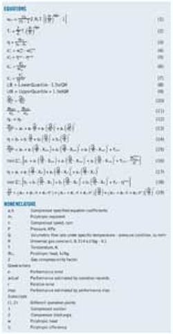
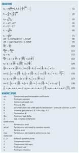
Equations 1-4 show the standard API formulas related to crude sampling.
Competition in marketing and trading crude oil is very high, placing a premium on quality control. Proper sampling also plays a great role in final price of oil sold. Reducing sample error requires increasing both the sample volume and homogeneity and maintaining the proper relationship between all sampling system elements. Sampling error cannot be eliminated, but it can be reduced by improving sampling techniques.
Sampling determines such physical parameters of a crude oil as specific gravity, vapor pressure, sediment and water content, sulfur, salt content, H2S, and viscosity. The typical purposes of sampling include customer satisfaction regarding composition, water content, and contaminant content, the completing and fiscal reports, and resolution of commercial or insurance claims.
Automatic sampling at Khark normally gathers 10-15 l. Some of the sample is subject to laboratory analysis. A 1-1. sealed sample is delivered to the captain. Another 1-1. sample is sealed and placed in cold, dark storage for at least 3 months. The main factors affecting the quality of sampling include the sampling location, hardware, and handling and analysis of the sample.
Manual sampling is an alternative but is problematic in its own ways. The quantity of free water in storage tanks must be determined. Extra care is required in handling, mixing, and storing the samples. The uniformity of sample fill rates and volumes must be maintained by the operator. Errors in determining the level and sampling point in the stream must also be avoided. And a relatively large amount of time elapses en route between the sampling point and the laboratory.
Proper extraction and representative sampling requires an autosampling system to ensure:
• Proper positioning of the autosampler with regards to the custody transfer point.
• Line-content homogeneity.
• Flow-proportional sampling.
• Proper sample handling and laboratory mixing.
• Accurate laboratory analysis.
• Occasional performance testing.
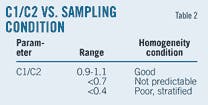
In all conditions stream profiling should be 1.1>C1/C2 >0.9. The sampling system should be designed such that these parameters are met even in worst-case conditions.
Conditions for representative sampling include:
• Taking the sample from the middle of the flow line.
• Homogeny and good mixing.
• Flow-proportional sampling.
• Low alteration of physical properties of fluid in sample such as pressure, viscosity, and density.
• Sample volume of 10-15 l. and grabs of 1-1.5 cc.
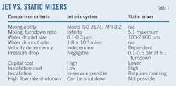
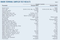
Table 1 explains the influence of sampling and mixing systems on loading rate and of fluid velocity and piping orientation on sampling point.
Sampling system
Differences in density between crude oil and water, particularly at low velocities, cause water flow movement in the bottom of the pipeline to take a stratified shape. At low flow rates homogeneity is weak. Preventing phase separation and improving the mixing ratio and homogeneity in sample points required installing an additional mixer.
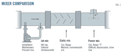
Figs. 1-2 show the mixing system and piping elements.
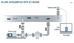
Dynamic (jet) mixers run a branching pipe from the bottom of the line, pressurize the liquids extracted, and re-inject them upstream against the general flow.
Fig. 3 shows typical positioning of a jet mixer.
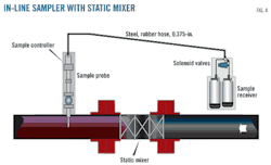
Static mixers use vanes to create additional flow turbulence. The flow passing through the vanes creates pressure drop across the mixer.
Fig. 4 shows the static mixer in an in-line sampling system.
The most prevalent auto-samplers in the crude industry are:
• Jet mix autosampler (Cojetix).
• Fast loop sampler.
• Shipboard sampler.
• In-line sampler (as used at Khark terminal).
Cojetix uses the standard dynamic mixing method but pulls from the center of the flow to create a mixing area, homogeny, and a mixed phase between water and crude. To minimize cross contamination the sloped steel tube between the sampler and the receiver is short. At the end of sampling dead volume is negligible.
The fast loop autosampler creates suction and discharge via pump at the same point on the annulus, making one tapped connection on the pipeline enough. Systems sometimes use a combination of Cojetix and fast loop sampling.
Portable shipboard autosamplers are used during ship-to-ship operation. Individual samplers should be installed for each manifold. Proper sampling requires adjusting the loading rate of each manifold to near equal. With proportional sampling the variation of flow rate should be less than ±10%.
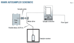
Khark terminal uses Cliff Mock Model C in-line auto-samplers with a 2-in. probe. The samplers are mounted horizontally in the center of the pipeline downstream of the oil metering station. They use the isokinetic sampling system to take representative samples from crude oil during the tanker loading, transferring them to 18-l. receivers via a 0.375-in. diameter hose.
Khark's in-line samplers use piping elements as a mixing system. Fig. 5 shows a schematic of Khark terminal's crude oil samplers. Fig. 2 shows the mixer piping element installed before the autosamplers.
Testing
Research calculated and drew the graphs for C1/C2 ratio vs. flow rate for the entire autosampling system at Khark. The C1/C2 ratio measures the concentration of water at the top of the pipeline vs. against that found at the bottom (Table 2).
Equations 5-9 (API standard formulas) generate Fig. 6, showing flow rates of both heavy and light crudes and the C1/C2 ratio.
Khark's autosampler functions better for heavy crude than for light. When the flow rate is more than 6,000 cu m/hr, C1/C2 remains within tolerance. T jetty autosamplers exposed to the same flow rate as samplers at Azarpad yield a better C1/C2 because of differences in the meter-run size of the piping element mixer.
For the same flow rate the C1/C2 ratio decreases from heavy to light crude oil, mixing energy and dissipation being greater for light crude. Treating this problem in low flow rate sampling required modifying the system by installing an extra mixer. Instead of adding another piping element Khark used a rim rotor-type turbine meter and pipe straightener.
The sampler proving test injected pressurized seawater into the Azarpad during light and heavy crude loading to tanker at minimum possible crude flow rates. The test apparatuses contain a water meter, a 1-in. quick action valve, elbow, check valve, fitting, and hose pipe.
The test procedure injected a set amount of water in a finite time before the sample position and performed laboratory analysis of water content at the sample receiver. Data from multiple test helped compute a standard deviation (Equations 10-13) and results were compared with the API standard table.
Tests lasted about 2.5 hr and were repeated two times. Water entered the system at rate of 67 gpm injected on top of a strainer about 20D before the sampling point. Table 3 shows data and test results. Allowable deviation for a single sampler is ±0.09 for total water content of 0.5%, One of the samplers was within these parameters on light crude but not on heavy crude.
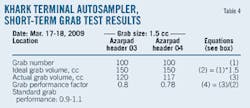
A test of short-term performance factors used the expected sample for a user configurable grab count vs. actual sample for that grab count. Table 4 shows the results of the short-term grab performance test for Azarpad autosamplers, a few of which fall within an allowable limit of 0.9-1.1.
Table 5 compares shore tank sampling and the Cojetix autosampler. The results show higher uncertainty in the shore tank sampling.
Results
Comparing Khark's in-line single autosamplers with mixing piping element test results with the latest version of standard C1/C2 curves shows acceptable homogeneity at loading rates >6,000 cu m/hr, but found that at low loading rates enough mixing was not occurring within sampling, requiring addition of an extra mixing element. Figs. 3-4 show recommended modification systems. Equation 9 also shows mixing energy varying with flow rate, the increase in loading rates creating additional mixing energy.
Cargo loading rates at Khark exceed 6,000 cu m/hr more than 90% of the time, so it has acceptable performance in normal operations. To decrease cross contamination, the length of the 0.375-in. diameter hosepipe between the sample extractor outlet and container should be minimized. The connection hose should have sufficient downward slope towards the receiver can to minimize collection error. A scale can help evaluating sampling performance.
The distance between the probes and custody transfer at Azarpad jetty complicates taking a representative sample. Two approaches may resolve the line fill issue: sample the line fill in a separate receiver or ignore the problem.
Existing dead sample volume on the Azarpad sampling system can compensate for ignored line fill samples. The in-line sampler with piping element works best using the nearest meter to run samples at the start and completion of loading, and any other generally low loading rate, decreasing the mixing ratio and homogeneity.
Using this sampling system for 100,000 b/d of crude transfer can save about $1.7-3.5 million/year, with $300,000/year realized when handling condensate. Maximizing these savings, however, requires periodic testing of the sampling system, with water injection being the best available testing mechanism. Maintaining the accuracy of sampling will also increase customer satisfaction.
Table 3's results show one sampler operating at near 1 m/sec velocity accepted and the other rejected, confirming the unpredictability of mixing in slow flow rate conditions. Comparing Table 3 with Fig. 6 also shows the C1/C2 ratio as not adequate for checking the sampling system, making the water injection proving test mandatory.
The authors
Manuscripts welcome Oil & Gas Journal welcomes for publication consideration manuscripts about exploration and development, drilling, production, pipelines, LNG, and processing (refining, petrochemicals, and gas processing). These may be highly technical in nature and appeal or they may be more analytical by way of examining oil and natural gas supply, demand, and markets. OGJ accepts exclusive articles as well as manuscripts adapted from oral and poster presentations. An Author Guide is available at www.ogj.com, click "Submit an article." Or, contact the Chief Technology Editor ([email protected]; 713/963-6230; or, fax 713/963-6282), Oil & Gas Journal, 1455 West Loop South, Suite 400, Houston TX 77027 USA. |
More Oil & Gas Journal Current Issue Articles
More Oil & Gas Journal Archives Issue Articles
View Oil and Gas Articles on PennEnergy.com
