Despite the promulgation of multiple standards regarding materials and methods used in pipeline construction and the adoption of these by contractors and operating companies, pipelines can and do fail. The current rapid expansion of pipeline networks globally (OGJ, Feb. 9, 2009, p. 52) combined with a constrained pool of qualified labor in the oil and gas industry as a whole (OGJ, July 20, 2009, p. 34) only heightens the importance of preservice inspection and testing.
This article details a recent case in China in which pipeline flaws were only discovered during internal pressure testing.
Background
A leak occurred at 4.3 MPa during internal air pressure tests of a natural gas pipeline. A hole of about 500-mm diameter was found above the leak position, which lay 3 m underground.
Crews used down-direction welding technology to weld the 610-mm OD, 10-mm WT, grade X60 line pipe. FOX CEL 3.2-mm diameter welding rods acted as render first, then 71T8-Ni1 wire solders were adopted to fill weld and cover surface weld. Specification requires testing of new gas pipelines to 8.0 MPa.
Line pipe girth weld inspection conformed with SY4065-9,1 SY0401-98,2 GB/T9711.2-1999,3 SY/T4103-1995,4 JB4744-2000,5 and SY4056-93.6 Field inspection results of the girth weld offset measured 2.0 mm, beyond the 1.6 mm tolerance specified. The leaking girth weld was at the boundary between the area rolled and not rolled by a road roller (Fig. 1).
Two 30-40 mm samples of line pipe were taken from either side of the sample where the leak occurred. Test results showed a weld toughness of 96.7J at –20o C., according to the welding technique evaluation test result.
All the girth welds underwent X-ray inspection before the internal pressure test, and reinspection was done at the cracked girth weld. Failure analysis sought to determine the cause of the leak.
Macrofractography
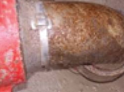
The crack originated from the weld toe and ran from 10 o'clock to 1 o'clock positions on the girth weld (Fig. 2): 280 mm long and 4.1 mm wide. There were obvious offsets at the position opposite the crack. Asphaltum protected the line pipe's outside and the inside surface was rusty.
| The left end of this cracked pipe section (left photo) was the bent side, with the right end the straight side (Fig. 2). The dark red belt lying close to the inner wall (right photo) shows the weld surface and the original flaw (Fig. 3). |
Opening the crack revealed a rough fracture, with an irradiation stripe along the inside surface and original flaws on the fracture inner wall (Fig. 3). The macrofracture morphology showed the crack originated from the original weld flaw on the inside surface, and the rupture took place suddenly during internal pressure test.
Measurements
Maximum offsets measured 4.5 mm at the crack position and 3.5 mm at the position opposite the crack (Fig. 4), beyond the tolerance of 1.6 mm specified in SY0401-98. The undercut was 1.4 mm deep and 50 mm long, not in accordance with a specified 0.5 = mm undercut tolerance.
Composition analysis
Chemical composition analysis showed the pipe body material to meet API SPEC 5L and the weld material in accordance with specifications for the wire solder and welding rod.
Tension, impact
Testing showed the pipe body's tension and impact properties in accordance with API SPEC 5L. Pipe body toughness at –20o C. measured 189.6 J. Disqualification weld porosities of 4 mm in diameter appeared on the tension specimen's fracture. SY/T 4013-1995 disallows single or decentralized porosities ≤ 3.2 mm diameter. Impact energy measured only 13 J in the weld at –20o C., far lower than the welding technique evaluation test result.
Metallography
Metallography samples came from the crack origination, crack tip, and position opposite the crack. Severe offsets and undercuts existed on the weld, and many cracks on the toes and undercuts at the crack origination and tip (Figs. 5-6). The original weld cracks extended during the internal pressure test, with the rupture originating from the original toe crack and causing the leakage. The deformed microstructure feature at the crack tip showed shear stress bore vertically on the weld.
| This image (left photo) shows the crack morphology at the undercut bottom of the fracture tip at 25× magnification (Fig. 5). A 100× magnification (right photo) of the fracture tip shows the toe crack (Fig. 6). |
Microfractography
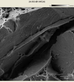
Microfractography specimens came from the crack origination and crack tip. The crack originated at the inner weld. There were weld dregs, weld flaws, and weld porosities at the fracture origination area (Figs. 7 and 8). The extended area of the fracture consisted of brittle cleavage and porosities.
Cause analysis
The pipe material conformed to standard. The girth-weld cracks related to weld quality and load borne by the pipeline. The causes of girth weld cracks are analyzed as the following.
The pipeline cracked at the girth weld. The stress resulting in girth weld cracking came mainly from internal pressure and structure stress borne by the pipeline.
The internal pressure of 4.3 MPa at the crack is only 53.8% of the 8 MPa specified. Axial load stemming from the internal pressures, however, was evidently sufficient to cause the girth-weld crack. Supposing all axial loads from internal pressure acted on the girth weld, Equation 1 calculates the axial load.
The actual axial load from internal pressure, however, measured far less than the 1,176 kilonewton (118 tons) calculated in Equation 1 because the pipeline was buried 3 m under ground compacted by a road roller and stratum restricted the pipeline.
Equation 2 calculates joint capability of the girth weld according to weld tension strength and pipe cross area.
Calculations show axial load of only 10.8% of weld connection capability even if all axial load from internal pressure acted on the weld, suggesting the girth weld could not have cracked at 4.3 MPa internal pressure without severe weld flaws.
Structure stress
Vertical displacement of 30-40 mm existed between the two cutting sections of the pipe sample with the cracked weld. Deformed microstructures were at the crack position, demonstrating large vertical structural stress at the cracked weld. Accumulated structural stress on a pipeline can increase any cracking tendency. The girth weld's position at 10 o'clock-1 o'clock is consistent with the direction of structural stress, suggesting the structural stress accelerated the crack extension.
The road roller compacted the ground after the pipeline was buried, and the crack position lay just at the edge of roll area. Sinking of the ground as it was being rolled would cause the compressive load on the underground pipe, but the compressive load would not be borne on the section of line where the ground was not rolled, creating vertical shear stress at the boundary of rolling and not rolling (Fig. 9).
The large vertical displacement of the two cutting sections taken as samples and the deformed microstructure in the vertical direction at the crack position show a large amount of structural stress.
Main cause
Measurement shows severe offset and undercut on the inner wall of the weld. The maximum offset is up to 2.2 times specification, and the maximum depth of undercut is up to 2.8 times specification. Severe offset and undercut will reduce the efficient section, concentrate stress, and reduce pipeline capability. Equation 3 calculates stress concentration from offset and undercut.7
Equation 3 shows the stress at the weld measures 2.47 times the average stress because of offset and undercut. Cracks at the bottom of the undercut may cause the real stress concentration coefficient to be more than 2.47.
The crack began at the inner weld surface, where both toe cracks and weld flaws were present. The toe crack depth is 13% of the pipe WT. Not only do the toe cracks reduce the section, but they also produce severe stress concentration and result in cracks easily extending during service.
A fitness-for-service assessment using TGRC-AFSP software considered both simultaneously and separately the effect of cracks, undercuts, and offsets according to the weld flaws and test pressure. Fig. 10 shows the result, indicating the girth weld is unsafe in the presence of cracks, undercuts, and offsets.
Toughness plays a key role in evaluating weld quality. The higher the toughness, the more resistant to crack initiating and extending the weld seam is. The lower the toughness, the less resistant.8 Weld-seam toughness is only 6.9% of pipe body according to test results.
X-ray examination took place on all the pipeline's girth weld seams before the internal pressure test, potentially exposing disqualification flaws at the crack origination position. A combination of inadequate equipment and inexperienced inspectors shielded these flaws from detection. An offset of 2.0 mm also exceeded specification (≤1.6 mm).
References
1. Shi You Petroleum Standard SY4065-93, "Specification for ultrasonic test and quality grade of pipeline girth weld for petroleum and gas industries," Beijing, Standardization Administration of the People's Republic of China, 1993.
2. Shi You Petroleum Standard SY0401-98, "Specification for construction and check and acceptance for oil and gas pipeline engineering," Beijing, Standardization Administration of the People's Republic of China, 1998.
3. Guojia Biaozhun Tujian Recommended National Standard GB/T9711.2-1999, "Petroleum and natural gas industries steel pipes delivery technology qualification part 2: B grade steel pipe," Beijing, Standardization Administration of the People's Republic of China, 1999.
4. Shi You Recommended Petroleum Standard SY/T4103-1995, "Specification for weld and check and acceptance of steel pipeline," Beijing, Standardization Administration of the People's Republic of China, 1995.
5. Jian Biao Construction Standard JB4744-2000, "Specification for weld technology assessment of steel pressure vessel," Beijing, Standardization Administration of the People's Republic of China, 2000.
6. Shi You Petroleum Standard SY4056-93, "Specification for X-ray photo and quality grade of steel pipeline girth weld for petroleum and gas industries," Beijing, Standardization Administration of the People's Republic of China, 1993.
7. Institute of China Boiler and Vessel Inspection, Pressure Vessel Inspection, "Training-teaching material for pressure vessel inspector," Beijing, China Special Equipment Inspection and Research Center, 2003.
8. Lu, S., Han, Y., Qin, C., and Yuan, P., "Crack and fitness-for-service assessment of ERW crude oil pipeline," Engineering Failure Analysis, Vol. 13, No. 4, pp. 565-571, June 2006.
The authors
Yuan Peng-bin is a senior engineer at Shanghai Hail Oil Tubular Goods Research Institute. He graduated with a BS (1983) in metal material sciences from Shanxi Mechanical Institute. He has 27 years' experience on aspects of failure analysis, inspection, and research of oil country tubular goods.
Lu Shuanlu ([email protected]) is a professor and specialist on failure analysis in the material department of the Mechanical and Electrical Engineering Institute at China University of Petroleum, Beijing. He graduated with a BS (1983) in metal material sciences from Xi'an Jiao Tong University. He has 27 years' experience on aspects of failure analysis, inspection, and research of oil country tubular goods.
Luo Faqian is a senior engineer at Tarim oil field. He graduated from with a BS (1987) in drilling engineering from Southwest Petroleum Institute. He has 23 years' experience in drilling engineering.
Kang Yanjun is a senior engineer at Tarim oil field. He graduated from with a BS (1983) in drilling engineering from Jianghan Petroleum Institute. He has 27 years' experience in drilling engineering.
Zhang Hong is a professor in the material department of the Mechanical and Electrical Engineering Institute at China University of Petroleum, Beijing. He received a PhD (1982) in mechanical engineering from China University of Petroleum. He has 28 years' experience in the research of oil country tubular goods.
Jiang Tao is an engineer at Tarim oil field. He earned a BS from Sichuan Finance and Economics School (1991) and has 19 years' experience in oil country tubular goods technology and management.
More Oil & Gas Journal Current Issue Articles
More Oil & Gas Journal Archives Issue Articles
View Oil and Gas Articles on PennEnergy.com


