CLOSED-LOOP CIRCULATING—1: Advanced pressure control improves kick, loss detection
David Pavel
Brian Grayson
Weatherford International Ltd.
Houston
Closed-loop circulating provides pressure control in many drilling and completion applications for which conventional fluid return systems are inadequate.
Flexible and scalable to the task, these systems redefine well control with advances in event detection and management and new capabilities for acquiring geophysical and petrophysical data.
Pressure control while drilling and completing a well is fundamental to operational and economic success for exploration wellbores, where drillability is often at stake, as well as in development wells for reasons of economic viability.
In all cases, risk mitigation and the safety of personnel, the environment, and the rig are paramount.
This first in a series of four articles examines the fundamentals of a closed-loop system and its inherent data-acquisition advantages in detecting problematic kick and loss scenarios. The next part in this series will examine manual pressure control in a closed-loop system.
The remaining parts will cover the use of automatic control to manage the mass flow balance across the entire wellbore and how companies are applying closed-loop pressure data to well plan optimization and completion enhancement.
All components of the closed-loop systems described in this article series are proven in the field. The newest of them, the automation of managed pressure drilling (MPD), has been applied successfully in more than 80 wells worldwide.
First used in 2006, companies have used automated MPD on land, jack up, platform and floating rigs to drill exploratory and development wells. These wells include both vertical and horizontal designs and many well conditions, including high pressure-high temperature, depleted zones, and mud weights varying from 9 to 18.8 ppg in oil, synthetic, and water-based muds.
Closed-loop system
With a handful of easily added rig components, engineers are solving persistent, almost elemental well-control problems to greatly reduce risk, improve drilling efficiency, and gain new insights into the wellbore.
Closed-loop circulating is central for eliminating open mud returns that have dominated drilling since introduction of rotary rigs. Despite its long, venerable heritage, open circulating is unable to meet the operational and economic demands of modern wellbore construction.
In marked contrast, closed-loop circulating offers a scalable set of capabilities that resolve many problems inherent to open systems.
These solutions range from early kick and loss detection to wellbore control and management, and they provide advanced data for optimizing the well plan and enhancing the completion. The change to a closed-loop system in wellbore construction follows a path taken long ago by other industries where contained, pressurizable systems are common for providing advantages ranging from safety and efficiency to process control and data acquisition.
On a rig, closing the loop means capturing and redirecting what is otherwise the free flow of drilling fluids, cuttings, and hydrocarbons from the drill pipe-casing annulus. This change results in immediate and dramatic advantages over conventional circulating.
Once captured, what was just flowing mud becomes a highly sensitive instrument. Instead of trying to ascertain wellbore effects and events through reading cuttings and flow volumes dampened by hours of bottoms-up time and fluid chemistries, engineers work with precise, high resolution and—most importantly—actionable, real-time pressure and flow data that improve decision making for determining the proper action needed.
Closing the loop creates a contained circuit of the incompressible drilling fluid, so that a small change in bottomhole pressure due to a wellbore influx or loss is transmitted by the incompressible drilling fluid to the surface in seconds. This is true whether the change is due to connection gas, formation breathing, or the beginning of a loss or a kick.
The closed-loop also allows for easy measurement of fluid flow. The total mass of this flow—what is pumped in vs. what is pumped out—is calculated quickly to describe minute circulating losses or gains.
The overall result of these measurements provides a sensitive window on the wellbore. With this window, a response can be rapidly tailored to many conditions and objectives— and without interfering with the rig's blowout preventer and fluid handling.
Integrating tools
A closed-loop system incorporates a few basic components that provide a scalable response that includes conventional drilling scenarios as well as managed pressure drilling.
Most tools used for creating a closed loop are standard proven rig equipment and have been available for decades (Fig. 1). They include rotating control devices, flowmetering technologies, drilling choke manifolds, and downhole isolation valves. The exception is the addition of sophisticated software and controls (used for years in a variety of other industries) that integrates these tools as a single system for monitoring, analyzing, and managing wellbore pressure.
Individually these tools aid the drilling and completion operations and increase overall safety. But when these components are paired or used in combination with each other, these tools greatly escalate the benefits of a closed and pressurizable mud return system.
The key enabling technologies for a closed-loop system are a rotating control device and data-acquisition instrumentation and software. This basic system for listening to the well—at high resolution and in real time—provides the means for early kick and loss detection. In addition, because the majority of well-control incidents occur during tripping operations, the closed-loop system commonly includes a downhole isolation valve that protects against swabbing while pulling the drillstring out of the hole.
The downhole valve is a remotely operated flapper valve that is installed in the casing string as a permanent or retrievable component for enabling selective isolation of the wellbore. As the rig trips the drillstring in and out of the hole, the valve is opened or closed to allow tripping the string at conventional speeds.
Faster trips reduce delays that can exacerbate hole conditions and lead to a well-control event. Faster trips also reduce associated non-productive time.
Listening to the well for early kick and loss detection is the most basic closed-loop application. The next level up is control, which is provided with the addition of a manual choke manifold. Adjusting back pressure through this annular choke allows the driller to dynamically control pressure and flow.
Adding an automated choke provides more precision and finesse in managing pressure. Integrated with instrumentation and software, the automated choke forms a supervisory control and data acquisition system for managing the entire annular pressure profile and flow.
The emerging frontier for pressure control lies in the predictive capabilities enabled in a closed-loop system. The use of enhanced pore-pressure prediction by real-time calibration of predictions using surface and downhole measurements optimizes drilling and well planning.
Integration with other instruments, such as specialized mug logging gas chromatographs for characterizing hydrocarbons, further extends capabilities. By capturing this reservoir information, closed-loop systems are helping provide geophysical insights that optimize completions.
Kick, loss detection
Early kick and loss detection within a closed-loop is employed with either conventional drilling methods or with MPD. While advantageous in all drilling applications, early detection of wellbore pressure fluctuations is particularly important in deepwater operations.
Such operations pose greater risks for people, the environment, and the rig. These operations typically have narrower drilling windows, more difficult drilling, and rig rates that are a huge cost component of overall costs. For these operations, closed-loop systems offer advantages for improving both safety and efficiency.
A drilling kick is the main operational danger for the crew, the environment, and the rig. The second greatest risk is a misdiagnosed kick. The complication results from the fact that kicks commonly involve fluid loss. This pairing forms a difficult cycle of repetitive kicks and losses that generates much nonproductive time for fighting the well and increases the risk of a major well-control event.
With the delayed action inherent in an open mud-return system, the procedure for mitigating a kick once detected involves circulating a higher weight mud into the well. In anticipation of a kick, the driller may pump heavier mud as a margin of safety.
While this may control the influx, a heavier mud commonly has the drawback of slowing the rate of penetration. But the real downside of weighting up is adding a heavy mud that exceeds the fracture gradient and initiates a fluid loss—in which case, the response is to lighten the mud weight but, we hope, not enough to initiate yet another influx.
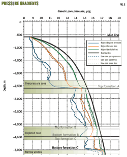
This kick-loss scenario, a back and forth effort to balance the equivalent circulating density with formation characteristics, is a common and costly problem with conventional circulating systems. It is exacerbated greatly in difficulty and expense by the narrow drilling windows that characterize construction of deepwater wellbores (Fig. 2).
In deepwater well construction, the numerous casing points required for isolating narrow drilling windows add costs ranging from pipe to the rig required to handle these casing strings.
An RCD in the loop
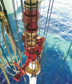
Adding a rotating control device to form a closed-loop system facilitates the timely acquisition of information that enables fast identification of wellbore changes and a mitigation of problems early in their development (Fig. 3). This is achieved either through traditional changes in mud and employing the blowout preventer or by initiating managed pressure drilling operations.
The workers are next to a rotating control device on a deepwater riser (Fig. 3).
Safety is also enhanced mechanically. As it has since it was first developed, the RCD redirects annular flow from under the rig floor and away from crew and equipment where it can be contained effectively.
By identifying kicks and losses when they first begin and volumes are still small, drillers can control the wellbore before the kick or loss volumes become large and the events escalate to become a well-control problem. This action reduces risk, improves safety and economics, and minimizes remediation time. The value of this information is important, if not essential, to safe and efficient rig operations and well construction.
On a recent well drilled from a semisubmersible, Weatherford provided early kick detection for a conventional, overbalanced drilling operation. The system identified the onset of a kick, but at the time conventional indicators did not support the diagnosis. During the delay caused by ensuing decision-making, the kick grew, control measures failed, and ultimately the drillstring and bottomhole assembly became stuck and the hole was lost. The correct information was at hand. Had it been acted on expeditiously, the influx could have been mitigated before it became a serious problem.
The advantage presented by a closed-loop system is the distinction between proactively controlling the well and reactive well control. There are two aspects to this proactive control:
1. Acquiring actionable, real-time pressure information.
2. Ability to act on it.
Both begin with using an RCD to close the loop.
The industry has applied RCDs for more than 4 decades. Early applications were in air drilling operations where the RCD diverted air, cuttings, and hydrocarbons away from the rig via a blooey line. The industry soon recognized the safety afforded by this containment and redirection and drillers quickly adopted it to fluid circulating systems
Installed above the blowout preventer, an RCD has elastomeric sealing elements and a bearing assembly to provide a pressure-tight barrier between the wellhead and the drillstring. This barrier eliminates open-to-the-atmosphere mud returns to create a closed-loop system. With the RCD in place, drilling fluids, cuttings, and hydrocarbons safely circulate out of the annulus without interrupting operations.
In 2010, researchers statistically linked RCD use with reducing well-control events. They found "consistent statistical evidence, across a variety of regression models and variable specifications, that the use of RCDs decreases the incidence of blowouts."1
RCD design has evolved with various models developed to address such factors as pressure, temperature, and wellhead diameter. Recently developed are next-generation marine RCDs for riser applications on floating rigs. The purpose-built technology addresses the unique deepwater requirements for installation and maintenance, as well as heave compensation. The first marine RCD, Weatherford Marine 7875, is also the first to be API certified.
Micromeasuring wellbore flux
Containing the rig's fluid system within a closed loop provides a source of high-resolution data. Using standard pressure and mass flowmeters, companies can quickly acquire precise information such as minute changes in bottomhole pressures that reach the surface in seconds and detect almost immediately volume variations as small as a few gallons. The closed-loop allows for the reliable measurement of these microfluxes while circulating, drilling, tripping, making connections, and stripping.
Thus identified, the driller can mitigate these precursors to kick and loss events before they have a chance to develop into something more serious. In addition to real-time data, decision-making benefits from an analysis of actual data vs. predicted downhole environments. Remote viewing of data also enhances decisions by easily including offsite experts in the process.
This data acquisition and analysis combined with an RCD for early kick and loss detection describes the most basic configuration of Weatherford's Microflux system for analyzing microchanges. The system includes proprietary algorithms to analyze flow and pressure data (Fig. 4).
The screen capture shows the signature for a downhole fluid influx in real-time. The first sign of an influx is increased return flow at the surface. The suggested best practice is at the top along with data tracks indicating (white line on right) the amount of surface pressure required to suppress the influx. The red line on the left indicates that the driller has successfully restored the mass balance (Fig. 4).
On a fixed rig, the system has detected kicks with only 0.25 bbl of influx. On a floating drilling unit, where vessel movement had introduced a 25 bbl/min peak-to-peak variation, it detected a kick with less than 3 bbl of influx.
Testing the system
The Louisiana State University PERTT laboratory conducted a series of full-scale tests for assessing the performance of Weatherford's early detection system in water-based and difficult oil-based muds. The tests for a vertical well using full-scale equipment clearly demonstrated the system's ability to detect influxes and losses at very low volumes.
With oil and synthetic-based fluids and open mud return systems, a longstanding concern has been that solubility can delay kick detection.
In tests, a flowmeter-equipped closed-loop system detected gas kicks in oil-based mud of less than 0.5 bbl of influx volume. The tests found that density trending helped differentiate downhole influxes from gas expansion at surface, and accurate return flow monitoring during connections helped identify abnormal conditions such as swabbed gas and ballooning.
Several other tests explored other possible uses of the system. These included dynamic leak-off and formation integrity tests, behavior with multiple simultaneous kicks inside the wellbore, and identification of ballooning or breathing during connections.
The positive lab tests led to field applications. The first two wells drilled with the system were a shallow exploratory well that used water-based mud and a difficult development well drilled with oil-based mud.2 3
The wells confirmed the system's ability to identify changes in flow on a real-time basis. Also identified were processes for screening potential kicks and loss data when the rig was not drilling and for addressing anomalies created by pipe movement.
The system also successfully detected small influxes during connections as well as swabbed in kicks. At more than 12,000 ft in the oil-based mud, the system detected small deviations in flow when the pumps were shut down to make a connection.
References
1. Jablonowski, C.J., and Polio, A.I., "The Impact of Rotating Control Devices on the Incidence of Blowouts: A Case Study for Onshore Texas, USA," Paper No. SPE 133019, Trinidad and Tobago Energy Resources Conference, Port of Spain, June 27-30, 2010.
2. Santos, H., et al., "First Field Applications of Microflux Control Show Very Positive Surprises," Paper No. SPE/IADC 108333, Managed Pressure Drilling & Underbalanced Operations, Galveston, Mar. 28-29, 2007.
3. Santos, H., et al., " Kick Detection and Control in Oil-Based Mud: Real Well-Test Results Using Microflux Control Equipment," Paper No. SPE/IADC 105454, SPE/IADC Drilling Conference, Amsterdam, Feb. 20-22, 2007.
The authors
More Oil & Gas Journal Current Issue Articles
More Oil & Gas Journal Archives Issue Articles
View Oil and Gas Articles on PennEnergy.com
