Study pinpoints hydrate causes at Iranian cracking centers
F. Esmaeilzadeh, O. Dehghani, H. Rajaee
Chemical Engineering Department
School of Chemical and Petroleum Engineering
Shiraz University
Iran
Simulation with Aspen Technology Inc.'s HYSYS indicates the formation of hydrate crystals in a de-ethanizer tower is likely due to the presence of water. This phenomenon happens at the top of tower where the temperature is 5° C. and pressure is 15 bara.
Separation of C2 gasses and those lighter than liquid C3+ occurs in a valve-tray tower at Iran's olefin cracking center, the Jam petrochemical complex at Assaluye, Bushehr. As Fig. 1 shows, liquid hydrocarbons from the cracking compressor center and C3+ from liquid storage enter this tower as the main feed via liquid driers that eliminate most of the associated water.
Since the water in the hydrocarbons is not separated completely and less than 80 ppm leaves the driers, water enters the tower with hydrocarbons.
The internal temperature profile drops to 5° C. after the internal tower condenser (Fig. 2). At this point, in the presence of methane, ethane, hydrogen, ethylene, and some propane and propylene, any water present results in formation of hydrate Type I at the top of tower. This presence of water under these operating conditions is unusual but, according to thermodynamic rules and simulation results, predictable.
Water is a strong polar molecule that is repulsed by nonpolar hydrocarbon molecules. This repulsion appears with a high increase in activity coefficients. The repulsion force is maximized under a slight concentration of water molecules in the liquid stream on the trays. The concentration of water maximizes the activity coefficient of water (extreme dilution). This high amount of activity increases the water molecules' volatility and explains the presence of water in top of tower.1
The presence of water molecules beside methane, ethane, and ethylene molecules under low temperature and high-pressure conditions increases the chance of hydrate crystallization. The obstruction of lines leads to release of about 7.7 tons/hr of hydrocarbons to flare. If the average price of ethylene is $700/ton, this flaring results in a loss of nearly $1.2 million/month, an estimate for hydrocarbons that go to flare from the top of the tower when the line is choked by crystal hydrate.
This article suggests practical ways to eliminate the obstruction and prevent wasting the gas from the top of de-ethanizer tower. After study of several methods, we concluded that using a suitable inhibitor besides renewal of the dryer's filters (water-drop filter) and changing of the sequence time of dryers are the best ways to prevent hydrate formation in a de-ethanizer column.
Gas hydrates
Gas hydrates are crystalline, nonstoichiometric, clathrate compounds. They form when the gas contacts water under favorable temperature and pressure conditions. Gases that can form hydrates include natural gas compounds such as CH4, C2H6, C3H8, i-C4H10, CO2, and H2S. Also N2, O2, noble gases, and hydrocarbons such as cyclopropane can form hydrates.2
The water molecules in the hydrates form a cage-like crystal structure through hydrogen bonding around the entrapped gas molecules. The gas hydrate structures are designated as Type I, Type II, or the recently determined Type H.3 2 Type I and Type II have two types of cavities and structures, while Type H has three types of cavities.2 4 5
Formation of these crystals and line obstruction accompanied by an increase in pressure can burst processing lines and lead to an explosion.2 4 5
Conventional ways to prevent hydrate formation include:
• Changing the processing conditions of the operating unit so that the hydrate would not form; for example, by changing the temperature and pressure.6
• Eliminating water from the gas mixture to prevent free water forming.5
• Using inhibitors.6
• Using steam tracing or electrical tracing to raise the temperature above the hydrate formation point.1
De-ethanizer stripper
In the de-ethanizer, condensed hydrocarbons enter the tower from the fourth step of cracked-gas compressor in order to separate C2 compounds and those lighter than C3. This tower incorporates two other lines besides the feed line: One of them is the feed line for compounds heavier than propane and three-carbon derivatives; the other one, for offgas compounds that include those lighter than propane and comes from the propylene separation unit.
The main feed of condensed liquids leaves the high-pressure compressor (Stage 4) and enters at Tray No. 2 at 33.8 tons/hr. The C3+ compounds enter the tower in Tray No. 8 at 11 tons/hr, and finally the offgas compounds enter the tower at maximum 3 tons/hr. The main feed that enters Tray No. 2 passes a two-phase coalescer before entering the tower, in order to eliminate existing free water. It then enters the guard driers to reduce the water content to 1 ppm.7
The other feed flows contain no water molecules because of how they are produced. The bottom product is sent to the final separation unit of C3 cuts at 40 tons/hr, and the top product, including components lighter than C2, leaves the top at 8 tons/hr.
Simulation conditions
Using HYSIS, we first modeled the tower in static mode. Moreover, we tried to select the suitable fluid package to satisfy all thermodynamics conditions indicated by laboratory results of tower products.
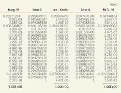
After checking different methods with such experimental methods as SRK-SRK, Margulies-PR, NRTL-PR, m-PR-m-PR, and Lee Kesler- Lee Kesler (Table 1), we observed that the new modified PR equation facilitated a complete simulation. As a result, the outlet product values, using the new modified PR equation of state in the simulator, are well suited with the experimental values.
Top and bottom tower temperatures were key variables in this simulation because the temperature of tower is the easiest parameter for controlling the operation. After determining an adequate package, we input the actual conditions and compositions into the software according to the experimental data and checked the outlet streams' composition against the experimental values.
As expected, water appeared in the top of the tower. We investigated the conditions for hydrate formation and reported the possibility of hydrate formation in the top of the tower.
Preventing hydrates
The simulation results showed that the effective parameters for preventing hydrate formation involve the column's top temperature and pressure. Following are suggested ways to set these operating parameters in a safe range:
• Isolate the tower overhead line to maintain the temperature above hydrate formation.
• Use electrical or steam tracing to maintain the temperature above hydrate formation.
• Decrease the internal condenser duty to increase the top temperature of tower.
• Decrease the tower pressure to decrease the temperature to less than hydrate formation.
• Eliminate water content in the inlet feed by either absorption or adsorption.6
The important adsorbents are silica gel, silica-based beds, activated alumina, alumina gel balls, and molecular sieves. This study used a mol-sieve bed to eliminate water from liquid hydrocarbons and decrease the dewpoint of this stream to –85° C.
• Use methanol or ethylene glycol as an inhibitor. The proper inhibitor should be selected for the operating conditions, especially temperature, because in very low temperatures, glycols become viscous. The temperature of the cold box downstream of the control valve in the top of the tower is about –40° C.
In this situation, methanol could be used as a hydrate inhibitor.6 Since the hydrate forms at 5° C., using of methanol has no advantages. Besides, a high amount of methanol can result in off-specification products.
De-ethanizer stripper
Fig. 1 illustrates that the de-ethanizer tower of the JP complex is a valve-tray column with three feed streams.
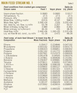
Liquid hydrocarbon from the cracking compressor enters Tray No. 4 at 33,858 kg/hr. Table 2 shows some of the important thermodynamic conditions of this stream.
The C3+ stream comes from liquid storage at 10,985 kg /hr. Table 3 shows some of important thermodynamic conditions of this stream.
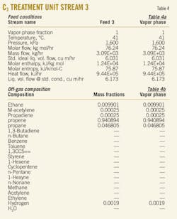
An offgas stream from separation of the C3 cut, flowing at 3,100 kg/hr, enters Tray No. 22. Table 4 shows some of important thermodynamic conditions of this stream.
Feed No. 1 enters the tower via a two-phase separator drum and a liquid drier, facilitated by a molecular-sieve bed, for adsorption of hydrocarbon water (Fig. 1). The operating pressure of tower is about 15 barg. The temperature profile of this tower changes between 92.5° C. in the bottom and 5° C. after internal exchange at the top of the tower (Fig. 2).
This internal condenser is cooled by propylene. The temperature of the sensitive tray (No. 7) should be adjusted to 60° C. under normal conditions; this parameter was respected in this simulation.
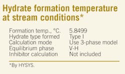
As a result, Fig. 3 illustrates the mole fraction of water on each tray. According to the selected fluid package and regarding the water content of feed No. 1 (50 ppm), the equilibrium temperature of hydrate formation is 5.8499° C. Since the normal temperature of tower at the top is 5° C., the probability of hydrate formation is clearly very high (box below).
The predicted hydrate is Type I in this simulation. (Type I has two types of cavities and structures.) It was determined that, if water is present in the tower entrance, hydrates will form.
Preventing hydrates was investigated and is summarized in the following:
1. Using electrical or steam tracing. The line is maintained warm with electrical or steam tracing. Since this line goes to the cold-box exchanger, this method results in a high amount of thermal loss and doesn't have high efficiency. However, in the cold box exchanger (downstream of top control vale), the water content of this stream will transform to ice and will have more problems.
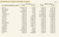
2. Column pressure reduction. This method results in changing the top and bottom streams' compositions. Table 5 shows that when the column's pressure is decreased to 13 barg from 15 barg, the stream's composition is changed mainly. For example, ethane in bottom of tower increases to 1.12E-04% from 5.29E-05%. This is undesirable.
3. Inhibitors. In this method, methanol was examined as a hydrate-formation inhibitor, but the location of the injection point after the control valve at the top of the tower was recommended by the manufacturer. Since the methanol should be injected before the hydrate formation point (before the control valve), using methanol is impractical, and we should send the product of the top of the tower to flare to control the tower pressure.
In order to meet our company's operating conditions in this case and the computations, the amount of methanol needed to prevent hydrate formation in a de-ethanizer tower can be taken from the methanol available for removing crystals in the cold section of cracking unit. In addition, the facilities (injection pump) for methanol injection was also available in the unit.
Since the methanol injection pump injects 0.55 cu m/hr of methanol, we can calculate the amount of injection for releasing obstruction in one stage. Since the methanol should be injected every 2 hr when needed (meaning every time we faced a line choked by hydrates), it is calculated as shown in the box below.
This amount of injection could be a problem for other products in which the methanol should be less than 10 ppm.
The other method in this case is to use ethylene glycols. Ethylene glycols are better for two reasons: The amount of injection is much less, and it is accessible for us because it is produced in our company. But in cold lines, glycol viscosity causes difficulties, and therefore operators often prefer methanol.
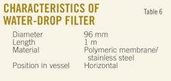
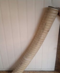
4. Using water-drop filters. The other method is using water-drop filters in the two-phase separator (D1 in Fig. 1), which were changed and increased the dryer efficiency. After the new filters, much free water was separated in the coalescer. Table 6 shows the characteristics of this new filter; Fig. 4 shows a new water-drop filter used in the vessel.
5. Adjustment of dryer sequence. The most efficient way to minimize the hydrate formation in top of the tower was to adjust the dryer's sequence. With this method, the time required for the line at the top of the tower to become choked by hydrate formation and the amount of injected methanol were checked for 1 month.
In this period, the dryer routine change was 48 hr (meaning the dryer was changed routinely every 48 hr). In the operation report, about each third day, we have one choking and methanol injection. More choking occurs in the end of the run time of the dryer before 48 hr. Fig. 5 shows this.
After this observation, we decided to decrease the sequence time of dryer change to 40 hr from 48 hr regarding a fixed regeneration time.
Acknowledgment
The authors are grateful to the Shiraz University for supporting this research. OGJ
References
1. Kister, Henry Z., Distillation Troubleshooting, Hoboken, NJ: John Wiley & Sons Inc., 2006.
2. Sloan, E.D. Jr., Clathrate Hydrate of Natural Gases, New York: Marcel Dekker Inc., 1990.
3. Englezos, P., "Clathrate Hydrates," Industrial and Engineering Chemistry Research, Vol. 32 (1993), p. 1,253.
4. Sloan, E.D. Jr., "Natural Gas Hydrate," JPT, Vol. 43 (1991), p. 1,414.
5. Sloan, E.D. Jr., Happel, J., and Hanto, M.A., Natural Gas Hydrates, New York: Academy of Science, 1994.
6. Kohl, A.L., and Riesenfeld, F.C., Gas Purification, Houston: Gulf Publishing Co., 1985.
7. Technip data base and operating manual, 2003.
The authors
More Oil & Gas Journal Current Issue Articles
More Oil & Gas Journal Archives Issue Articles
View Oil and Gas Articles on PennEnergy.com
