A new nonlinear predictive approach allows natural gas pipeline reciprocating compressors to respond rapidly to changing processes by omitting undesired or dangerous operating steps, preventing costly compressor shutdowns or component failure.
During an investigation of interstage pressures, a stepping algorithm allows examination of volumetric efficiency, rod loading, and other variables, thus predicting appropriate load-unload steps. Applying the algorithm results in effective process loading and unloading and safe compressor operation.
Maximizing compressor throughput, bounded by equipment and pipeline protection parameters, involves establishing an automated unloading-loading sequence that directs the compressor through a linear series of steps. These steps include opening or closing volume pockets and opening or closing cylinder-end deactivation valves. When torque control is automated, however, the control scheme must also prevent the compressor from operating outside design parameters for rod loading, volumetric efficiency, compression efficiency, wrist-pin reversal, and cylinder temperature.
A typical automation solution will reduce the compressor's ability to respond to process upsets, with some steps in the unloading-loading sequence becoming unsafe. The compressor could also automatically shut down as it fails to mitigate conditions of the process upset.
Maintaining a compressor within design parameters is particularly important for compressors built with deactivation valves that allow the cylinder to switch from double-acting to single-acting and vice versa. This importance stems from the increased risk of excessive cylinder and discharge temperatures and wrist-pin reversal while the cylinder is single-acting.
Despite this increased risk, cylinder deactivation remains a popular control measure because many modern compressors are built with relatively small cylinders that don't provide for a sufficiently large number of volume pockets to get a large torque range from a compressor. Cylinder deactivators, therefore, are critical in many installations for exploiting much larger torque variability than the range afforded by volume pockets alone.
Finding the next step in a cylinder's unloading-loading sequence unsafe under most circumstances prevents the compressor from moving beyond its current configuration due to linear treatment of the unloading-loading sequence. The inability to move beyond a given configuration prevents the compressor from responding to a variety of process upset conditions. Advanced control algorithms, however, allow the control system to assess steps beyond a given unsafe step within the unloading-loading sequence. Should a safe step be found, the algorithms then command the compressor to skip the unsafe state and move directly to the next safe step.
This nonlinear approach works both when the control system loads and unloads the compressor unit. While examining compressor status under a given set of conditions, operators with the relevant facts (i.e., torque curves) might find a safe step outside the linear loading sequence that provides better throughput than the current step.
This article will examine the operation of a compressor (Table 1) automated for a large northeastern US natural gas transmission pipeline that uses the described nonlinear control scheme. A fixed-speed electric motor drives a dual-service compressor, with each service having two stages. Each cylinder uses one or two fixed-volume pockets positioned on its head end along with crank-end deactivation valves, allowing them to be either dual or single acting at any given time. Regardless of the number of stages or services, however, any compressor equipped with either volume pockets, deactivators, or both may take advantage of the advanced control system discussed in this article.
Nonlinear torque control can operate in parallel with a speed control system, such as a variable-speed engine or variable frequency drive compressor. Advanced torque control would exert coarse control of horsepower, while speed control fine-tuned operations to smooth the pressure and flow output of the compressor. The combination would maintain driver speed at its most efficient during normal operating conditions.
Background
This article discusses a two-stage reciprocating compressor with two delivery services equipped using fixed-volume pockets and cylinder-end deactivators. Fig. 1 shows a simple process block diagram of each service connection.
The reciprocating piston compressor is the most widely used equipment for gas service.1 It consists of a double-acting piston with pressure-actuated check valves controlling the flow for both suction and discharge, allowing compression on both sides of the piston. Speed changes, addition of cylinder clearance, deactivating cylinders, and control of valve closing allow for variable management of displacement and direct control of throughput and loading. A compressor operating in this manner can convert more than 85% of horsepower to increased pressure.1
Fig. 2 shows the ideal compression cycle of a reciprocating compressor.
Deactivating a cylinder end reduces load in proportion to the number of cylinders in the compressor. If not properly controlled, this reduction may create a larger-than-anticipated horsepower drop. That drop may lead to inefficiencies in throughput and loading. Torque control can also regulate compressor load and throughput, providing the most effective method of maintaining throughput at rated horsepower.
Designing a control system to obtain optimum performance and reliability from a reciprocating compressor requires careful monitoring of compressor health. Rod load curves and peak rod load-reversal values can reveal overall compressor health. Rod load is loosely defined as the maximum force a compressor assembly can withstand. Additional definitions2 include:
• Combined rod load. The sum of actual gas load (including valve and passage losses) plus inertial loads at the crosshead pin in the direction of the piston rod.
• Gas load. The force resulting from the internal pressure in each chamber acting on the associated piston and cylinder head surfaces.
• Rod reversal. The shortest distance, measured in degrees of crank revolution, between each change in sign of force in the combined rod-loading.
Fig. 3 shows typical rod load curves for the subject compressor.
Safety issues
Personnel protection always overrides control protection. Operating parameters for personnel protection should coincide with rated values for the equipment. Proper monitoring of discharge pressure is the most important safety precaution regarding personnel. If discharge pressure rises above rated values, a pipeline rupture could occur, not only damaging property, but also threatening loss of life or severe injury to individuals. Properly setting up control strategies for a reciprocating compressor requires prioritizing objectives as follows:
• Ensure safety.
• Maximize throughput.
• Maintain load parameters.
Avoiding catastrophic failures of the compressor requires installing controls to maintain the system within safe operating limits. Many factors can cause catastrophic failure in a compressor. Operating safely requires maintaining these critical variables:
• Suction pressure above acceptable level.
• Discharge pressure below maximum pressure.
• Rod loading below maximum level.
• Discharge temperature below maximum level.
• Brake horsepower below compressor maximum horsepower.
• Volumetric efficiency (Ev) above a set point.
• Compression ratio above a set point.
A safe system will also monitor for acceptable signals from transmitters, lube-oil systems, vibration systems, scrubber levels, transient high-current conditions, cooling tower faults, service rod reversal faults above the rod reversal set point, motor faults, high suction and discharge temperature, high service rod loading, high cylinder discharge temperature, and extremely low Ev value.
Control strategy
The control system on the subject pipeline maintains a throughput set point (represented as percentage of torque) during changing input and output conditions to prevent shutdowns due to system upsets. The control system loads and unloads the compressor as required to maintain flow and keep the compressor operating within design parameters.
The compressor station is in most respects a common set up of two, two-stage compressors driven by the same crankshaft, using both fixed volume clearance pockets and crank-end deactivation valves to achieve a high degree of throughput variability. Being driven by a constant-speed electric motor increases the system's flexibility.
Advanced control algorithms treat each stage independently when performing many of the safety calculations for the current step, the next unloading step, and the next loading step. Each stage consists of one or two cylinders having different dimensions from the cylinders associated with the other stage. Each service also has a distinct unloading-loading sequence and is treated independently for load or unload decision making. Stage 1 on Service 1, however, has two identical cylinders and Stage 2 of Service 1 also has two cylinders of the same size with the same number of pockets, allowing for simplification of the calculations.
Breaking down the unloading-loading sequence for each service into lookup tables exposes the configuration of each relevant cylinder for each of the four stages (Table 2). Cylinders are either single or dual-acting and have opened or closed fixed-volume clearance pockets. Configuration allows derivation of active clearance, maximum end clearance, cylinder displacement, and parasitic BHP loss due to cylinder-end deactivation.
The same electric motor, however, drives the four stages: two for each of the two services. Preventing overloading requires adding the horsepower generated by all the stages. Comparing the total bhp for all stages to a set point determines whether further loading is permissible and desired, unloading is required, or the machine has arrived at the torque set point established by the operator.
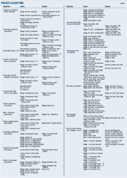
Examining the compressor's current step determines clearance of a stage, after which control algorithms use the relevant suction pressure, discharge pressure, and motor speed to calculate other important data points (Table 3). Examination first corrects and converts pressure and temperature readings, Vendor-, customer-, and manufacturer-generated tables, along with standard equations, then allows derivation of the compression ratio. Examination then determines compression efficiency, compression rod loading, tensional rod loading, wrist-pin reversal, minimum volumetric efficiency, and brake-horsepower. Checking these data points against set points verifies the safety of the step within the compressor's unloading-loading sequence.
The control logic then examines the next load step and the next unload step within a given service's sequence. The process treats the next load and unload steps identically, first finding the clearance for the next step, then calculating and using interstage pressure, clearance, temperatures, and speed, computed with the same approach as the current step. If the next step is permissible the controller selects it as the next load step for the compressor.
While these calculations occur, a similar set of calculations is performed for the next unloading step. The control system can then determine whether it needs to load, unload, or remain in the current step by comparing current torque and current pressures with their respective set points. When current torque is below the set point minus a deadband, the control system will choose the load step. Should current torque exceed the set point plus a deadband, or pressure exceed the pressure set point, the controller will choose the unload step.
Between initiating each load step or unload step, the control system waits for a set period of time to allow the process to settle. Unload steps usually require more wait time, load reduction usually taking longer to reach a steady state.
If the current step has acceptable pressures and the compressor is at the torque set point within the deadband, the control system will elect to do nothing. If, however, either the next load step or the next unload step are unacceptable, then the next step in the service's unloading-loading sequence is examined in the same manner. Using the pressures of the previous estimate instead of the current pressures allows estimating interstage pressure with the new clearances.
The step-checking continues until an acceptable step is found or all steps have been exhausted without finding any acceptable steps. Until an acceptable next step is found, the compressor will remain in the current step. Most controllers, however, can check all loading steps and unloading steps long before the load or unload inhibition expires.
The checking system will allow the operator and technician to modify set points, parameters, and constants to optimize its function. Most systems use deadbands to anticipate control variations. A greater than anticipated fluctuation within narrow deadbands, however, may lead to nuisance shutdowns because of overshoot conditions.
Use of theoretical set points may also lead to nuisance shutdowns due to unanticipated mechanical factors. Discharge pressure may spike, for example, because of downstream conditions not yet taken into consideration.
On site data from the compressor run-in may show the set points and dead bands as inappropriate for the current physical environment. Using data to generate set points and deadbands is therefore recommended.
Aging equipment and changing operating conditions may require set points be changed over time, requiring the systems to be monitored continually so that set points can be optimized.
References
1. McKinney, G.D., "Compressor Station Basics," Energy Management Services, 2009.
2. "Rod Load Calculations and Definitions for Reciprocating Compressor Monitoring," GE Power Orbitiz, Vol. 28, No. 1, January-March 2008, http://www.gepower.com/prod_serv/products/oc/en/orbit/downloads/1q08_reciptips.pdf.
The authors
More Oil & Gas Journal Current Issue Articles
More Oil & Gas Journal Archives Issue Articles
View Oil and Gas Articles on PennEnergy.com
