Fiber optic sensing can help reduce third-party threats
Properly specifying and selecting a distributed fiber optic sensing system during a pipeline's design stage and developing a rapid-response team to react to any third-party threats will increase a pipeline operator's ability to prevent third-party damage, improving pipeline integrity.
Distributed fiber optic sensing methods support continuous real-time monitoring of pipeline rights-of-way based on precisely localized measurable effects caused by third-parties and other external interference such as vibration, sound, strain, and temperature.
The total number of pipeline leaks in Europe has dropped over the past few decades.1 2 Third-party, external interference, however, remains the main cause of spill incidents. Traditional leak-detection systems can detect third-party threats only once they've caused actual leaks. Preventing such leaks therefore requires additional online pipeline-integrity monitoring.
Background
Governments, engineering companies, and industry associations have developed standards and regulations to apply to design, operation, and maintenance of pipelines and thus ensure safe operation. But land movements, earthquakes, tree roots, floods, illegal tapping, construction works, and various other third-party events, whether intentional or unintentional, all continue to affect pipelines. These make perfect pipeline integrity impossible and raise the value of quickly locating and minimizing any spills.
The most common technology for continuous, real-time leak detection is computational pipeline monitoring. CPM systems analyze real-time supervisory control and data acquisition information such as pressure, flow, and temperature to estimate the hydraulic behavior of the transported medium. This allows leak-related anomalies and leak location to be detected, with certain accuracy restrictions during transient operational conditions.
The key to avoiding leaks due to third-party interference and other external threats, however, is to detect the threat in time to intervene. Various right-of-way monitoring strategies and technologies exist, including walking the pipeline, airborne flight surveys, and satellite surveillance. But these checks are spot checks only and further improvement of the pipeline's integrity can be achieved only by more frequent and more real-time-related online monitoring methods.
After a short analysis of two industry organizations' reports on leak causes, this article will provide a short overview of available online monitoring methods and the technical principles, applications, and design considerations for distributed fiber optic sensing.
Leak statistics
The oil companies' European association for environment, health, and safety in refining and distribution (CONCAWE) has collected spill data on European cross-country oil pipelines since 1971 (Table 1). About 70 companies and agencies operating oil pipelines in Europe provide data for CONCAWE's annual survey.1 These organizations operate more than 150 pipeline systems, which, at the end of 2007, had a combined length of 34,721 km.
CONCAWE reported nine spils in 2007, corresponding to 0.26 spills/1,000 km of line, slightly less than the 5-year average and well less than the long-term running average of 0.55, which has been steadily decreasing over the years from a value of 1.2 in the mid-1970s. Of the nine reported incidents in 2007, two were related to corrosion and seven were connected to third-party activities either accidental or malicious.
The previous CONCAWE report recorded 12 spillage incidents for 2006, half of which were related to mechanical failure, 2 to corrosion, and 4 to third-party activities.
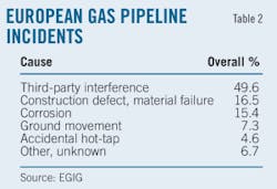
The European Gas Pipeline Incident Data Group provides similar annual statistics (Table 2).2 Transmission companies of 15 European countries collect incident data on almost 130,000 km of gas pipelines every year.
The 7th EGIG report shows the main cause of incidents as third-party interference, which caused 48% of incidents over the past 5 years. The total number of incidents declined, reflecting improvements in materials, design standards, operator skill, and right-of-way maintenance, but third-party interference and other external threats still caused roughly 50% of all leaks.
Only by improving right-of-way monitoring will it become possible to detect external threats in time to intervene before a leak occurs. Achieving this goal requires increasing the monitoring frequency from today's typical weekly or even monthly airborne surveys to online and real-time methods.
On line systems
CPM systems use the pipeline's intrinsic SCADA instrumentation and communication system to achieve online monitoring. All other systems are extrinsic because their sensors have to be installed in addition to standard pipeline instrumentation.
Acoustic sensing methods use the sound waveguide features of the pipeline. Microphones attached to the pipeline at predefined intervals detect the sound of an excavator touching the pipeline and determine its location.
Sensor cables installed along the pipeline change their electrical parameters due to reaction of the cable sheath with the spilled medium and work as leak-detection and location systems. Vapor monitoring systems use porous tubes installed along the pipeline that allow vapor gases to enter. At regular time intervals, the gas inside the tube moves into gas analyzers allowing leaks and their location to be detected.
All these systems require installation of sensors and analyzers together with power supply and communication facilities every few kilometers. Only distributed fiber optic sensing methods span over more than 30 km and ones that allow detection of third-party interference and other external threats without visual monitoring before they endanger the pipeline.
Fiber optic cables
Fiber optic cables are standard equipment for transmission of voice, video, and other data and are frequently installed along pipelines to enable communication between and remote control of individual stations. These fibers, however, can also measure several physical effects with high local resolution along cable stretches of up to 20 or even 30 km.
Fiber optic cables typically minimize scattering to maximize transmission distance and rate. Some scattering effects, however, depend on the cable's ambient conditions, temperature, strain, etc. (Fig. 1).3
• Rayleigh scattering: elastic scattering of light based on density and composition fluctuations within the cable material that is not sensible to ambient conditions.
• Raman scattering: inelastic scattering of photons due to molecular vibration within the cable material. As the magnitude of the molecular vibration is influenced by the environmental temperature, this effect can be used to measure temperature profile across the cable length.
• Brillouin scattering: based on time-dependent density variations of the fiber material. The wavelength of the reflected signal depends on the ambient temperature and the strain or vibrations of the fiber optic cable. The effect can be used to measure the temperature profile across the cable length as well as any cable strain changes and vibrations along the cable route. Ensuring measurement of just the temperature requires decoupling from any strain, as is done in standard fiber optic cables. Measuring strain requires application of two fibers, one fixed to the measurement object and one to measure the temperature along the first fiber.
Advanced optical time domain reflectometers measure these effects. These devices send short laser pulses into the fiber and analyze the time-distance related reflections with regards to frequency and amplitude of the desired scattering effect so strain or temperature profiles along the fiber can be created.
Typical commercially available temperature resolution is roughly 0.10 K, while strain resolution can be 20μ, both with a local resolution of about 1 m and the absolute range depending largely on cable construction. In all cases improvement of resolution corresponds to increased time for measurement making both application-specific.
A fiber optic configuration according to the Mach-Zehnder Interferometer can detect sound waves or vibrations by analyzing signal interference between two separate fibers4 and acts as a hydrophone (Fig. 2).
Sensor application
Distributed fiber optic sensors can monitor up to 40-60 km of pipeline from one location without an intermediate power supply. Loss of a transported medium due to pipeline leaks typically leads to:
• Local cooling due to Joule-Thomson effect (in high-pressure gas pipelines).
• Soil temperature change due both to the temperature difference between soil and emanated fluids and to evaporation effects.
• Detectable sounds, especially in high-pressure applications.
Distributed temperature sensing applied to natural gas, brine, phenol, sulfur, LNG, crude oil, and other mediums allows for detection of even small leaks.3 8 9 It is also independent of any transient process conditions or other operational drifts inside the pipeline, which can affect CPMs. Modern signal-analysis methods can even identify the periodic opening and closing of small leaks in gas pipelines due to freezing. Such methods can also detect leak sounds in offshore pipelines.8
Geohazards like earthquakes, landslides, and surface subsidence result in ground movement, further stressing the pipeline. Although it is increasingly standard practice to consider relevant route selections during pipeline design and perform intensified route surveillance, geohazards remain one of the main causes of pipeline leaks. The restricted real-time monitoring capability of current surveillance methods typically only identifies slow ground movements and not sudden movements, preventing the immediate pressure reduction or pipeline shutdown necessary to avoid a leak.
Distributed fiber optic strain sensors improve online surveillance capability of dangerous ground movements in two ways:
• Strain-sensing fibers attached directly to the pipeline measure wall strain and calculate resulting pipeline movement.5 6 Difficult installation, however, limits this method to only identified high-risk route sections
• Strain-sensing fiber optic cables installed parallel and close to the pipeline11 allow for indirect determination of pipeline stress and leak risk. A simpler cable-installation method allows this approach to cover large route sections and be applied easily to existing pipelines. Interferometer-based systems can also identify certain earth movements.
Third-party intervention
Third-party intervention causes the majority of all reported leaks. Such intervention includes construction and agricultural works, illegal tapping, and intentional damage. Avoiding leaks caused by third-parties requires detecting them in time to send out staff or security services to stop the intervention.
Applying distributed strain-sensing or interferometer-based hydrophones along the pipeline allows detection of approaching heavy earth working machines, digging (manual or machine-supported), metallic contact with the pipeline, and other sonic signals. Some vendors say they can detect people walking along or cross the pipeline route.8 9
As with all perimeter-intrusion detection systems, however, it is important to use advanced signal analysis algorithms and configure or train them. Not doing so properly will yield either a low detection rate or numerous false alarms. A Mach-Zender Interferometer monitors the environmentally sensitive and remote Bolshomi section of the Baku-Tbilisi-Ceyhan pipeline.4
Design, implementation
A combination of risk-based hazard and threat analysis, legal requirements, and results of environmental impact assessments typically serve as the starting points for considering installation of a distributed fiber optic sensing system. The pipeline purpose and construction, the pipeline route, its geology, weather conditions, and surroundings shape consideration of which sensors to use as well as the method and location of their installation. Fig. 3 shows typical locations of sensor cables relative to the pipeline.
If the groundwater level is below the pipeline, the sensor cables can be installed under the bottom to detect temperature changes due to leaking liquids. To detect leaks of most gaseous media, the top position is preferred. Measuring pipeline strain requires directly bonding the fiber to the pipeline. Typical gas and telecom cable positions are suitable for third-party interference and ground movement detection.
While most distributed sensing applications use standard single-mode fibers, sensing cable constructions vary considerably depending on the measured effects.5 Interferometers and temperature sensing may use standard telecommunication cables. Measuring strain and vibrations requires fixing the sensing fibers either to the central strength member or to the fiber sheath, which then is bonded to the pipeline wall. To improve detection time, special constructions for temperature measurement are also available.
Achieving a clear leak-detection signal in most applications requires a 2-5 K. temperature difference between the medium in the pipeline and the standard soil temperature around the sensor. Larger temperature differences will reduce detection time considerably.
Avoiding blind periods due to seasonal temperature changes requires each system be able to maintain a certain temperature difference throughout the year. While this is no problem for high-pressure gas pipelines (due to the strong Joule-Thomson effect), typical non-heat traced crude and product pipelines require a detailed seasonal analysis of soil temperature profiles.
Fig. 4 provides an example of a single-season scenario (winter, operating pipeline). It shows a model-based temperature profile for a crude oil pipeline, assuming a 33 °C. medium temperature and -10 °C. air temperature after several weeks of continuous operation, and allows estimation of the minimum necessary distance between the pipeline wall and the sensor cable.
In addition to the chosen sensor position, leak-detection time depends on leak position, leak size, temperature difference, and various soil conditions. Actual project-specific field tests should always come into play, particularly if the combination of theoretical simulation, calculation, and former experience do not guarantee the desired detection quality.
References
1. "Performance of European Cross Country Oil Pipelines," Statistical summary of reported spillages, CONCAWE, www.concawe.org, October 2009.
2. European Gas Pipeline Incident Data Group report, www.egig.nl, December 2008.
3. Inaudi, D., Glisic, B., Figini, A., and Walder, R., "Pipeline Leakage Detection and Localization Using Distributed Fiber Optic Sensing," Rio Pipeline Conference, Rio de Janeiro, Oct. 2-4, 2007.
4. FFT Secure Link: Installation Overview, Future Fiber Technologies Pty. Ltd, www.fftsecurity.com, 2009.
5. Inaudi, D., and Glisic, B., "Long-range Pipeline Monitoring by Distributed Fiber Optic Sensing," International Pipeline Conference, Calgary, Sept. 25-29, 2006.
6. Griesser, L., Wieland, M., and Walder, R., "Earthquake Detection and Safety System for Oil Pipelines," Pipeline & Gas Journal, Vol. 231, No. 4., December 2004.
7. Scott, S., and Barufett, M., "Worldwide Assessment of Industry Leak Detection Capabilities for Single & Multiphase Pipelines, Texas A&M University, OTRC Library, No. 8/03A120, Aug. 6, 2003.
8. Digital Pipeline Integrity Monitoring System—Application Guide, Sensornet, 2009.
9. Integrated Pipeline Monitoring—Integrity, Schlumberger, 2008.
10. Pipeline Integrity Monitoring—Transandean Route, Case Study, Omnisens, Switzerland.
The authors
More Oil & Gas Journal Current Issue Articles
More Oil & Gas Journal Archives Issue Articles
View Oil and Gas Articles on PennEnergy.com


