A proposed design can improve a production facility that handles sour crudes containing saline water. The design provides low crude oil shrinkage during stabilization and optimizes H2S removal, particularly in summer.
A project in the Middle East used the design, and this article discusses a case study for the design based on a similar Middle East crude and the same product specifications and ambient temperatures as in the actual project.
The case discussed has slightly different oil shrinkage values and cost savings than the actual project, but the final conclusions are the same.
Production facilities
For more then a decade, companies have based the design of production facilities for sour crude oil associated with saline water cut on the integration of desalting, production, gas gathering, and compression units.
Such integration has the advantage of further vapor recovery (control of rpv over upper and lower bounds), use of very low-pressure gas instead of flaring, H2S removal, and energy waste minimization all in one plant.
These production facilities have an optimized design based on capital and operating costs that meet oil stabilization and H2S-removal requirements.
These facilities typically have three-stage separation in which the third stage is a column with the dual-purpose function of H2S removal and crude stabilization.
In these designs, the recommended desalter location is between the second and third-stage separators. This location minimizes the energy required for reboosting the pressure at the desalter, achieves maximum recovery, and prevents fouling on stabilizer trays due to salt precipitation.
These facilities typically have used only a small proportion of the associated gas from crude stabilization as fuel gas while the rest is flared. Increases in gas prices, however, are now encouraging oil companies to gather most of the associated gas from the facilities and either inject it or use it for fuel.
Refineries also are dictating more stringent oil specifications in terms of salinity and H2S content, and these requirements have led upstream operators to modify many production facilities as well as use those specifications to design new projects.
Modifications include incorporating desalting, gas compression, and injection within or downstream of the production units. During the past decades, some projects have integrated all these units (production, gas gathering, injection, and desalting) to minimize the required energy as well as increase on-spec oil production.
This article summarizes design aspects and benefits of an integrated production facility when it is fed by a saline and H2S-rich crude oil. An improvement to this new integrated system is then proposed and evaluated against test cases.
Production facilities
Most conventional production facilities include a multistage separation scheme based on sweet crude. The scheme typically has three stages of separation, each with a different operating pressure.
The hydraulic requirements of providing free flow towards storage or production tanks without the need for installing excessive pumping equipment usually determines the third-stage pressure. The design normally bases the first and second-stage pressures, however, on linear optimization techniques.
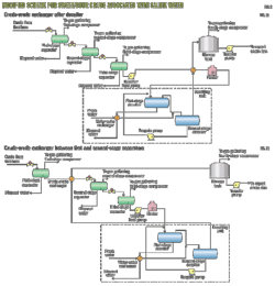
Fig. 1 shows a schematic of the conventional design for sweet crude without an appropriate rpv control during hot and cold seasons.1
To meet the rvp specification for export purposes (typically, 8-10 psia in summer and 9-11 psi in winter), the scheme will include a fired heater in the process or along the flowline to reduce crude viscosity and break oil-water emulsions for easier separation in the first and second-stage separators.
In most cases, optimizing the summer case pressure will result in lower rvps than the minimum specified limit. This normally is a consequence of the loss of n-butane and i-butane in the crude composition after the first and second-stage pressure let down. In most cases, a heater by-pass line cannot resolve this loss.
The process scheme can have the same configuration with minor modifications if the crude has a saline water cut. These modifications include the addition of a fired heater or crude cross exchanger to meet H2S and rvp specifications at the separator and desalter oil and temperature requirements for breaking the oil-water emulsions.2
Note that the location of the crude cross exchanger depends only on the nature of the crude oil.
With the arrangement shown in Figs. 2a and 2b, it is possible to meet the H2S and rvp specifications in the export oil; however, they might not provide an optimized solution for minimizing the crude oil shrinkage factor or maximizing the production of stabilized oil.
Stripper columns provide a robust alternative for H2S removal when a multistage-separation scheme cannot achieve the H2S specification. Nevertheless, many existing production facilities operate far from their optimum point because there is no requirement to meet the lower rvp or to recover associated gas.
In most multistage-separation schemes, the first two stages are three-phase separators that reduce water cut to about 5%. Desalting units with electrostatic forces then can remove the remaining water along with salt and sediments.
A design that fails to provide normal operating conditions and acceptable water cuts at the desalting unit inlet results in off-spec bs&w; hence, there is a need for fired heaters or cross exchangers in production facilities. Water removal from crude oil will increase the API gravity and consequently the oil price.3
Furthermore, operators that export oil to the world market need to comply with international bs&w specifications; therefore, their production facilities need to incorporate desalting units.
Integrated design
Integrated production facilities can achieve maximum oil recovery (minimum shrinkage), suitable conditions for desalting and H2S removal (typically down to 40 or 30 ppm), and minimum energy consumption and hydrocarbon emission.
The reduction of crude oil shrinkage while stabilizing the oil requires the scheme to control rvp within the higher and lower bounds.
A design can include integrated units for sour crudes with associated saline water cut. A main part of these facilities is a dual-function column that stabilizes the crude oil and, at the same time, strips out H2S.
As shown in Fig. 3, this column acts as a replacement for the third-stage separator used in a multistage design. For reboiling purposes, the design can include a direct fired heater or an indirect fired heater, such as a water-bath heater, although most designers prefer indirect heaters if the required heat duty does not exceed practical limits of their use.
It is not economical to install steam and demineralized water units in most production facilities, although if they exist by virtue of other reasons, they should be considered as an option. The article does not discuss the pros and cons of reboiling methods.
In many parts of the world, the crude oil temperature in flowlines differs greatly between the hot and cold seasons. Facilities, therefore, often have an air-cooled exchanger installed upstream of the crude-crude cross exchanger to eliminate the additional heat from the stabilizer bottom product (Fig. 3) and to manage the seasonal temperature changes.
The design for sweet crude oils would eliminate the H2S removal function from the stabilization column.
An additional feature of integration discussed in this article is the introduction of a compressor to allow recovery of tank vapors and boost the stabilizer pressure. The benefits of the compressor include not only the obvious vapor recovery but also that the compressor allows the stabilizer to operate at the most effective pressure for delivering optimum rvp and shrinkage values.
Case study
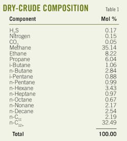
The case study uses the dry-crude composition shown in Table 1 and a molecular weight and density of C12+ of 390 kg/1,000 mole and 938.81 kg/cu m, respectively. The GOR at standard conditions is 462 scf/bbl.
The crude arrives at the production manifold at 350 psig with a maximum water cut of 20%. The estimated arrival temperature of the well fluid in summer and winter are 44° C. (111.2° F.) and 18° C. (64.4° F.) respectively. The measured ambient temperature of the area is 45° C. in summer and 15° C. in winter.
The production facility has a nominal capacity of 75,000 b/d oil at stock-tank condition with an rvp of 8-10 psia in summer and 9-11 psia in winter and an H2S of 40 ppmw.
In the past, desalting units required high inlet temperatures (100-120° C.) to ensure the cracking of the hydrocarbon-water bonds that subsequently led to oil-water separation. Thanks, however, to the evolution of electrode manufacturing technologies, this separation now is accelerated by more efficient electrostatic forces that allow for lower desalter operating temperatures.
Desalter manufacturers such as NALCO and Kvaerner state that minimum temperature of the desalting unit inlet stream can be as low as 72° C., while the minimum pressure is a few bars above the bubble point pressure. A pressure above the bubblepoint ensures that no gas forms inside the desalters after the stream pressure drop across the inlet mixing valves.
Pressure optimization
Our analysis used Aspen Hysys v.2006.5 software to simulate the entire process including the linear optimization of the first and second-stage pressures.
The optimization results for both the integrated design and multiseparation scheme suggested that the first-stage pressure has to be at maximum arrival pressure. An assumption of a minimum pressure drop of 10 psi for the upstream pressure control valve results in a 340 psig pressure for the first-stage separator.
Second-stage pressure optimization for integrated design converged at 140 psig at which the process recovered the maximum oil (Fig. 4).
The analysis optimized the third-stage pressure such that the column bottom pressure could provide enough head for overcoming the pressure losses across the air-cooled exchanger and cross exchanger as well as the friction loss and elevation heads.
Additionally, the higher column pressure led to increased rvp and oil recovery; however, this design could be difficult to implement for the following reasons:
• The stabilized oil generated a massive amount of gas at the production tank (5.5 MMscfd in the summer case) after the pressure dropped to tank pressure. This made it difficult for production tanks to handle the gas.
• The downstream temperature of the cross exchanger became so critical that if it exceeded 50° C. in summer, the export stream could not meet the H2S spec.
Despite these disadvantages, the column temperature was lower in this condition, and therefore, could eliminate the need for an air-cooled exchanger in summer.
One should note that the optimum design should cover all operational conditions such as summer and winter, although facilities in locations with long summer seasons can be operated and optimized under such a condition for most of the year.
Discussion
Streams with lower rvps than the lower bound limits (8-9 psia) lead to a loss of production while higher rvps restrict oil export due to safety considerations.
Simulations for the live oil used in the case study (GOR 462 scf/bbl) indicated that to have the maximum allowable rvp (further recovery) along with appropriate H2S removal, the stabilizer pressure should be as low as 37 psig. This pressure is sufficient for coping with the hydraulic requirements for transferring the stream to the storage tank.
The above mentioned pressure lies between two pressure ranges recommended by Moins4 5 and Maddox6 and closer to the one that Moins recommended.
Moins recommended a 30-45 psia range and emphasized it for H2S stripping, whereas Maddox recommended a 110-160 psia range for maximum recovery and minimum recompression horsepower.
Because the stabilizer in our case needed to meet export oil H2S specification together with maximum oil recovery by pushing the rvp to its upper limit, the optimized pressure approaches Moins's recommended range.
In most cases, it may not be feasible to meet both the H2S spec and the upper bound of the rvp spec for maximum recovery even by adjusting the stabilizer pressure and temperature. We therefore recommend for this configuration installation of a low-pressure compressor to inject butane-rich gas released from storage tanks back to the stabilizer column.
This compressor is not an additional item because one would have installed it as the fourth-stage compression in an integrated plant with gas gathering and compression. While in this scenario, the released gas from production tank feeds back to the stabilizer rather than directly to the third-stage compressor.
As mentioned previously, the gas from the production or storage tanks is usually n-butane and i-butane rich. These components will help keep the rvp in the specified range.
Increasing the column pressure can also improve the oil recovery. Because of difficulties of handling excessive amount of gas in production tanks, however, and critical control of cross exchanger's downstream temperature, facility operators do not always implement this.
As stated, allocating a compressor is not an extra cost to the overall field development provided that the development scope includes gas gathering and compression for injection or transfer.
A cold kickback line from the column's overhead stream routed to compressor suction will stabilize the compressor's operation during summer and winter and mitigate the risk of a vacuum in the production tanks.
The temperature of the crude oil from the flowlines varies during hot and cold seasons, while the process needs a constant desalter feed operating temperature irrespective of the season. One can accomplish this with installation of an air-cooled exchanger in addition to a crude-crude cross exchanger at the stabilizer bottom product line. The air-cooled exchanger will work together with the cross exchanger and provide the best operating temperature for the desalting unit and the production tank (Fig. 3).
During summer, the air-cooled exchanger cools the stabilized oil to storage conditions whenever the cross exchanger is partly or fully by-passed. One can switch off this air-cooled exchanger in winter if the stabilizer bottom product at the cross exchanger can provide the required heat to warm the desalter's feed.
Integrating a desalting unit inside a production facility also has the advantage of increasing the availability of stabilization units for long-term operations by eliminating the risk of salt precipitation and fouling on the column trays.
Table 1 compares a typical multiseparation scheme (Fig. 2a) and the proposed integrated design shown in Fig. 3.
For the comparison, we selected feed flow rates of 101,502 and 101,295 b/d with 20% water cut at standard conditions for summer and winter simulation cases, respectively. These numbers are equivalent to the mass flow rates shown in Table 2.
The comparison shows that fuel gas and power consumption increased by 501N-cu m/hr and 72 kw for the new design; however, the plant will produce more stabilized oil during summer. This comparison ignores the air-cooled exchanger's power consumption because it is not a major power consumer.
If one assumes a $0.7/MMbtu and $30/Mw-hr for fuel gas and the electrical power cost and the plant operates 8,000 hr/year, the extra operating cost for this new integrated plant during 30 years will be about $3.5 million.
Furthermore, the stabilizer, low-pressure compressor, and its suction drum impose an additional capital cost of nearly $1.3 million compared to a multiphase separation scheme.
Overall, the estimated cost difference between the two schemes is $3.3 million. On the other hand, the integrated design delivers about 300 bo/d (0.4% of the produced oil at stock-tank condition) increase in production during 6 months of each year. If one assumes a $40/bbl price for the stabilized oil, the revenue increases by $2 million/year. This means that facility will return the invested money within 2 years (internal rate of return of about 57%).
References
1. Herring, J.D., and Titsworth, B.J., "Improving Yield from Crude Oil with Improved Production Methods," 9th Arab Petroleum Conference, Dubai, Mar. 10-16, 1975.
2. Manning, F.S., and Thompson, R.E., Oilfield Processing of Petroleum Vol. Two: Crude Oil, Tulsa: Pennwell Books, 1995.
3. Arnold, K., and Stewart, M., Surface Production Operations, 2nd edition, Woburn, Mass: Butterworth-Heineman, 1998.
4. Moines, G., "Crude stabilization updated: Optimization of crude stabilization units," OGJ, Jan. 21, 1980, pp. 91-93.
5. Moines, G., "Crude stabilization updated: Stabilization process comparison helps selection," OGJ, Jan. 28, 1980, pp. 163-73.
6. Maddox, R.N., Erbar, J.H., and Shariat, A., "Distillation crude stabilization boosts recovery," OGJ, Apr. 23, 1979, pp. 71-76.
The authors
More Oil & Gas Journal Current Issue Articles
More Oil & Gas Journal Archives Issue Articles
View Oil and Gas Articles on PennEnergy.com


