NLNG maximizes LNG production in supply constraint
Nigeria Liquefied Natural Gas achieves a wide variety of operating modes, depending on the degree gas supply is constrained, with NLNG's 3 water-cooled liquefaction trains, 3 air-cooled liquefaction trains with waste-heat recovery, 10 gas-turbine power generators, in-train and common NGL fractionation units, and 5 condensate stabilizers.
Despite occasional shortfalls of gas supply from the Niger Delta, NLNG has utilized its flexibility to optimize energy consumption to utilize all available gas fully. Energy savings from optimization during constrained gas supply in 2009 resulted in gains of roughly 3.5% of LNG production.
Current configuration
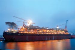
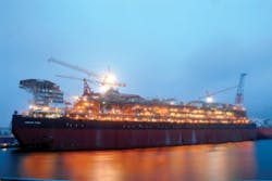
The Nigeria LNG plant on Bonny Island (Fig. 1) processes nonassociated and associated gas.1 Since start-up of the first two liquefaction trains in 1999, the plant by 2007 had grown to include six liquefaction trains, additional NGL fractionation, and associated utilities.
Despite availability generally greater than 95%, circumstances have at times resulted in a shortfall of gas supplied to the plant, compared with available capacity.
During a gas-supply constraint, optimization of energy efficiency has a large impact on operating profit because more than 90% of fuel gas saved can be processed into LNG, accounting for the energy consumed to liquefy it.
A number of different options for optimization are available at NLNG, due to the complexity of the plant and the magnitude of the gas-supply shortage. Before a descriptiion of a number of the options for energy savings, a general description of the facility is useful background.
Natural gas received at NLNG is separated from liquids before being routed to the six liquefaction trains. Within each of the trains, an amine unit removes CO2, followed by a molecular-sieve dehydration unit to remove water and a guard-bed for mercury removal to protect the downstream aluminum heat exchangers.
Liquefaction in all six trains at NLNG is based on the C3/MR process, in which mixed-refrigerant of methane, ethane, propane, and nitrogen cools natural gas to cryogenic temperatures and a separate propane circuit cools the refrigerant and precool natural gas. Each train has its own set of columns for fractionating NGLs condensed after the precooling section.
In addition, there is a common fractionation unit that can accept NGLs from all the trains in case the in-train capacity is constrained.
Several differences exist between Trains 1, 2, and 3 compared with Trains 4, 5, and 6 (Fig. 2).
Trains 1-3 use open-loop cooling water for final heat rejection from the propane-refrigerant circuit, whereas Trains 4-6 use air-cooling. This configuration yields a major efficiency advantage for Trains 1-3 because the propane condensing temperature against water-cooling is lower than it is against air-cooling, resulting in a lower head for the propane compressor. The design choice of air vs. water cooling is motivated mainly by the economics of initial investment and long-term supply of fresh water, which is evaporated in an open-loop cooling system.
A second difference is that Trains 1-3 fully liquefy the natural gas in the main cryogenic heat exchanger, whereas Trains 4-6 only partially liquefy it and then use an end-flash for final subcooling, with recompression of flashed gas to fuel.
A final major difference is that Trains 4-6 recover heat from the gas turbine's exhaust to heat regeneration-gas for the mol-sieve unit and via heat-transfer fluid for the amine and fractionation reboilers. Fig. 3 shows the breakdown of power consumption.
The sum of these differences results in Trains 1-3 being more energy efficient than Trains 4-6, mainly due to the effect of water-cooling.
Plant data
Fig. 4 shows daily average energy consumption as a function of LNG production for a wide range of production rates. The equivalent fuel usage for electric power consumed was calculated with the equivalent fuel consumed to make each unit of power (Mw) in the gas-turbine-driven electric generators.
Fig. 4 shows two groups of data, one for Trains 4-6 at high energy usage and high production capacity and the other for Trains 1-3 at lower energy usage and production. These same data are normalized in Fig. 5, which shows the equivalent fuel and power per LNG production.
Fig. 5 makes clear that even at maximum production rates, Trains 1-3 use a slightly lower percentage of energy per LNG produced compared with Trains 4-6. In addition, Fig. 5 illustrates that efficiency generally increases with increasing production rate, and turndown results in more fuel consumed per LNG produced. Fluctuations in ambient temperature cause the scatter in the data, as turbine and cooling efficiency depend on ambient air temperature.
A second feature of the data in Fig. 4 is that fuel consumption is generally independent of production rate when production falls to less than roughly 80%. At low refrigerant-circulation rates, the main refrigerant compressors begin to recycle gas in order to avoid compressor surge. During recycle, the energy spent compressing, cooling, and letting down pressure over the recycle valves dominates total energy consumption.
Interestingly, although Trains 1-3 are otherwise identical, Train 3 has a different compressor vendor, resulting in relatively more recycle during turndown, making it slightly less efficient during turndown compared with Trains 1-2.
Editor's note: The axes increments of Figs. 4-5 were removed by NLNG to protect "critical operating data or intellectual property."
Turning off trains
In any LNG facility consisting of multiple liquefaction trains, the simplest way to optimize energy efficiency is to turn off production trains that are not required to process the available feed gas.2 Turning off a train avoids compressor recycle, saving roughly 750 tonnes/day (tpd) of fuel gas when one of the larger trains is turned off. Once a train is turned off, however, it must be started again, which uses roughly one third to one half of a day's production of LNG to cool down. The simple payout time is thus about 7 days to turn off a train when it is not needed.
The benefit of running an extra train in case another train trips is a minor effect, as trips are relatively uncommon, and the typical restart time is short. At an LNG price of roughly $300/tonne, the benefit of turning off a train is roughly $200,000/day. The same principle applies to turning off two trains.
Preference is given to keeping Trains 1-3 on line because they are more energy efficient and produce refrigerant-grade ethane and propane, whereas Trains 4-6 do not. Turning off a train can be coordinated with noncritical maintenance requiring a shutdown of production.
Balancing trains
The case often arises in which a certain number of trains are required to process all available gas, but all trains cannot be fully loaded. In this case, production among the trains should be balanced to keep the compressors out of recycle.
The benefit of balancing production among trains is best illustrated by an example. At a certain total production, all six trains must process all gas, but not with the trains fully loaded. If all trains would be equally loaded with gas, Trains 4-6 would begin significant compressor recycle, while Trains 1-3 would not, simply because Trains 4-6 have a larger capacity.
When production is balanced to keep all trains equally out of recycle, a production adjustment of less than 1,000 tpd on each train can result in fuel savings of roughly 300 tpd, which, at an assumed price of ~$300/tonne of LNG cost roughly equals $90,000/day, or about $32 million/year.
Balancing of production among trains can be further optimized with relatively simple mathematical models. The data for fuel vs. production can be fit with a sloped line above the recycle point and with a horizontal line below the recycle point for each production train.
Thereafter the set of six equations for the six trains can be solved together for a minimum fuel consumption, subject to the constraint that total production must be possible with the total amount of gas available.
Using this logic, we have built a simple optimizer to find the best balance between trains, used by shift personnel in operations. Further, it may be possible in theory to use advanced process control to balance production among trains, particularly when some trains are in recycle operation.
Power generation
NLNG has 10 Frame-6 gas-turbine-driven generators capable of producing a total of more than 310 Mw, depending on the ambient temperature and turbine conditions. The total installed power (n+2) accounts for having one generator out of service for scheduled maintenance and having n+1 on line such that if one more generator trips, the total power demand will not suffer. During periods of constrained gas supply, power demand is reduced when some trains are shut off or when helper motors operate at reduced load.
As shown in Fig. 6, the fuel consumption of a gas-turbine generator is linearly dependent on the electrical power output. A linear fit to the data has a nonzero intercept at roughly 50 tpd fuel gas due to the heat lost to the turbine exhaust. Correspondingly, any of the gas-turbine generators also uses roughly 50 tpd of fuel during start-up when running at full-speed-no-load before the generator is excited to start giving electrical output.
This loss of heat mainly to the turbine exhaust means that roughly 50 tpd fuel can be saved for every generator that can be turned off when it is not needed, while keeping n+1 generators running in case one trips. Even at full design power demand, this means one generator should always be off either for standby or maintenance.
In practice, during constrained gas supply, two or three generators out of 10 are often unnecessary. The 50-tpd fuel savings from turning off one generator roughly equals $15,000/day, or about $5 million/year.
The fuel-gas pool is optimized in two ways. First, fuel gas is preferentially produced by the end-flash of Trains 4-6 rather than taking feed gas or scrub-column overheads—this minimizes the amount of LPG in the fuel gas, to maximize LPG production. Secondly, when the fuel-gas pool is nearly full from end-flash of Trains 4-6, the LNG rundown temperature is decreased to adjust the amount of flash gas produced to fuel.
Fractionation, stabilization
At maximum production in an LNG plant, there is generally a tradeoff between LNG production and NGL production. Generally the price of NGL (LPG and condensate) is higher than LNG, but an additional ton of NGL extracted costs more than an additional ton of LNG because the lower molecular weight LNG takes more power to liquefy at lower temperature.
During gas-supply constraint, however, when compressors may be partially recycling, it is generally effective to maximize NGL extraction as far as possible because the additional load on the refrigerant compressors only serves to move them away from recycle but does not result in more fuel consumption.
NGLs scrubbed from the gas before liquefaction are generally routed to the fractionation units within the train to produce propane, butane, and condensate. While Trains 1-3 can only export NGL, Trains 4-6 can export or import NGL.
Trains 1-3 and the common fractionation unit use heat-transfer-fluid heated in furnaces burning fuel, while Trains 4-6 use HTF heated by the gas turbine's exhaust. Comparing the fuel consumption of furnaces when in-train fractionation is running or not suggests that exporting the liquids of one of Trains 1-3 to Trains 4-6 would be worth more than $2.5 million/year in fuel savings that could be used to produce LNG.
NLNG has five condensate-stabilization units, three of which have reboilers heated by HTF. Plant changes are in progress to change the source of HTF from fuel-fired furnaces to the in-train waste-heat recovery of Trains 4-6, thus making heat used for stabilization free.
Furthermore, reboiler duties are generally minimized either through base-layer control or the use of Shell's Multivariable Optimizing Control, a form of advanced process control.
In summary, the best ways to optimize fractionation is:
1. Send liquids to Trains 4-6 for fractionation because heat there is free from the waste-heat recovery unit via HTF.
2. Use HTF from the waste-heat recovery unit for stabilizers.
3. Use APC to minimize reboiler duty for all running fractionation units.
Operations management
Clearly, minimizing flaring also generally maximizes profit by saving gas that can be converted to salable products. To this end, NLNG actively minimizes flaring upon start-up, plant trips, or passing valves.
Flaring from the cool-down of LNG ships that arrive warm is minimized by quenching with LNG and recompressing with boil-off gas compressors normally used for compressing boil-off gas from the LNG tanks, while excess boil-off gas from the tanks is processed by the end flash-gas compressors and routed to fuel gas.
When a plant's gas supply is not constrained, a simple key performance indicator such as gross heating value of products produced divided by gross heating value of feeds taken in can be useful for measuring energy efficiency.
During constrained gas supply, however, the efficiency by such a definition naturally decreases with decreasing throughput, simply due to the recycle over main refrigerant compressors. Thus, the gross-heating-value loss should always be minimized, but comparing one period to another can be misleading when gas supply rates and compositions are constantly changing.
When gas supply is uncertain, it is not always possible to plan production of all available feed gas. During the wait for return of supply, it is tempting to keep many trains running at the expense of wasted fuel gas rather than have to down-nominate suppliers for some hours while a train starts up.
A long feed-gas transmission network can buffer gas supply with line-pack while a new train starts up. Uncertainty in gas supply further complicates the planning of routine maintenance done during an opportune shutdown because it takes time to reassemble equipment before a train can be restarted.
Furthermore, only Trains 1-3 can produce refrigerant-grade products from fractionation, and thus there is a preference to keep them running over Trains 4-6 in addition to their better energy efficiency.
A number of additional energy-efficiency initiatives have been implemented at NLNG, similar to other sites.2 Fuel-gas usage in the main refrigerant compressors is generally minimized by controlling the ratio of MR to LNG, which also affects the LNG rundown temperature, via operator or advanced process control.
Off-line water washes of the gas turbines to restore available power are planned with opportune shutdowns. Similar to other sites, however, it has been noted that only a major maintenance inspection can restore full capacity. Work has been ongoing to minimize furnace duties for heat-transfer fluid and mol sieve regeneration gas.
References
1. For more information, see www.nlng.com.
2. Wilson, J., and Wal, G., v.d., "Leading the pack for efficiency and environmental performance, Oman LNG," GasTech 2008, Bangkok, Mar. 10-13, 2008.
The author
More Oil & Gas Journal Current Issue Articles
More Oil & Gas Journal Archives Issue Articles
View Oil and Gas Articles on PennEnergy.com
