Nodal analysis indentifies ESP wellhead choke problems
Based on a presentation to the 57th Southwestern Petroleum Short Course, Lubbock, Tex., Apr. 26-29, 2010.
As shown with a nodal analysis, the use of wellhead chokes on electrical submersible-pumped wells causes high hydraulic losses across the chokes and wastes considerable energy.
The analysis studied over-designed installations with negligible free gas production.
This article describes a proposed calculation model for determining the head required to produce well fluids to the separator and the liquid rate in the production system.
Artificial lift
The objective of artificial lift design is to determine a lift system with a liquid-producing capacity that matches the inflow rate to an oil well. Because the mechanical design of the lifting equipment uses a probable liquid rate, the designer needs a precise estimate on the production rate attainable from a well.
Design inaccuracies or improperly assumed well rates can result in a mismatch of the design and actual produced liquid volumes. The main cause of discrepancies between the designed and produced well rates, assuming proper design procedures are followed, is the improper estimation of possible well rates, for instance inaccurate data on well inflow performance.
The consequences of under or over-design of lifting systems can lead to the following:
• If the artificial lift equipment has a greater capacity than the well, then its efficiency cannot reach the designed levels and mechanical damage may also occur.
• If the well's productivity is greater than the lifting system capacity, an operator delays profits from the production.
Over and under design of artificial-lift installations occur often. An operator can adjust relatively easily after installation some lifting methods such as gas lift or sucker rod pumping because these methods have a broad operational range.
Electric submersible pump installations, however, do not tolerate design inaccuracies because an ESP has a restricted range of pumping rates. If used outside its recommended liquid rate range, the hydraulic efficiency of the ESP rapidly deteriorates and its efficiency can approach almost zero. In addition to the loss of energy and the consequent decrease in profitability, the ESP system, when operated under such conditions, soon develops mechanical problems that can lead to a complete system failure.
The usual outcome is a workover and the need to run a new ESP with a proper lifting capacity design.
A common solution for over-designed ESP systems is installation of a production choke at the wellhead. The choke, due to the high pressure drop that develops through it, limits the well's liquid rate so that the ESP operates in its recommended pumping rate range. This solution eliminates the need for running a new ESP with a correct capacity, thereby saving the costs of the pulling and running operations.
At the same time, however, the system's power efficiency decreases considerably due to the high hydraulic losses across the surface choke.
Wellhead chokes
In the majority of cases, oil field operators design ESP installations to run at a fixed electric frequency, usually 60 or 50 hz. This implies that the ESP runs at a constant speed that depends on the frequency and develops different heads for different pumping rates as predicted by its published performance curve.
Because installation design is based on the selection of the centrifugal pump, the head-vs.-pumping rate curve of the pump is an important design parameter.
When designing for a constant production rate, the designer selects a pump type with the desired rate within its recommended capacity range. Detailed calculations of the required total dynamic head (TDH) determine the number of required pump stages. TDH is the head required to lift well fluids to the surface at the desired pumping rate.
Thus, the designer can plot the head-vs.-capacity performance curve of the selected pump containing the necessary number of stages based on the performance of one stage.
For an ideal design when one knows all the necessary well and reservoir parameters, the pump will produce exactly the design liquid rate because it will work against the design TDH. In this case, the head required to overcome all pressure losses necessary to move well fluids to the separator equals the head available from the pump at the given pumping rate.
This perfect situation, however, is far from being universal. Often inaccuracies or lack of information on well inflow performance cause design errors, and the well produces at a rate different from the initial design.
The problem with the conventional design is that the ESP installation has a design for a single rate and not for cases with other parameters.
Nodal analysis can solve these problems easily for a system consisting of the well, the tubing, the ESP, and the surface equipment. Nodal analysis allows for calculation of pump heads for different possible pumping rates and determination of the liquid rate in the total system. This rate is at the head required to produce well fluids to the separator. The required head equals the head developed by the ESP.
Fig. 1 compares the conventional design with that obtained with nodal analysis. Conventional design involves the calculations of the TDH at the design rate only. From this rate, the designer selects the type of the ESP and the number of stages accordingly.
The ESP system's stabilized liquid rate will be different from the design target if well inflow performance data were uncertain or missing during design. Nodal calculations, however, can predict the required head for different liquid rates—the dashed line in Fig. 1. The well's actual production rate is at the point where the required head equals the available (provided by the pump) head.
A typical situation occurs when the final liquid rate is more than the target rate, indicating inaccuracies in the well performance data assumed during the design. A higher rate production is not allowed because reservoir engineering considerations dictate the well's required production.
The cause of the problem (Fig. 1) is that the actual head requirement (actual TDH) is much less than the calculated design TDH. The only solution of the problem, if pulling the ESP and replacing it with a properly designed one is not desired, is to install a choke at the wellhead to limit the liquid rate.
The pressure drop across the choke, indicated by the head drop in Fig. 1, must be sufficient to supplement the system's actual TDH to reach the TDH used for the original design. This artificially increases the head requirement of the production system and the ESP will produce the desired liquid rate.
Nodal analysis
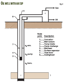
A designer can apply readily systems analysis (nodal) principles to the analysis of wells produced by ESPs. Fig. 2 shows the production system of an ESP installation with node points.
System components, connected by the nodes indicated in the figure, are formation (a), well section between the perforations and the ESP (b), ESP (c), tubing string (d), flowline (e), surface separator (f), liquid column above the pump (g), and gas column in the annulus (h).
These components work together when the well produces a stabilized liquid rate to the surface. Determining this rate is one of the basic applications of nodal analysis. The five steps required for the calculations are:
1. Select a solution node. This can be any node point in the system and its proper selection facilitates the evaluation of different assumed conditions.
2. Select a range of liquid flow rates for subsequent calculations.
3. Starting from the two endpoints of the system (Node 1 and Node 6 in Fig. 2) and working towards the Solution Node, calculate the flowing pressure at every node for the first assumed liquid rate.
4. Repeat the calculations in Step 3 for each assumed liquid flow rate. The Solution Node has two sets of pressure-rate values and these values represent the performance curves for the two subsystems at the Solution Node.
5. Determine the liquid flow rate under the given condition, which is the intersection of the two performance curves according to a basic rule of systems analysis that says that the inflowing and the outflowing pressures at any node must be equal.
For the case investigated in this article, the Solution Node is at the ESP's discharge (Node 4 in Fig. 2) and the analysis uses the coordinate system head vs. rate. In this coordinate system, the given ESP's performance curve represents the head available from the pump at various liquid rates.
The performance curve for the remainder of the production system, representing the head required to produce the given amount of liquid, however, must be calculated and plotted as given in the following sections.
Intersection of the two performance curves will determine the stabilized liquid flow rate developing in the entire production system.
Determining liquid rate
To apply systems (nodal) analysis to the ESP installation, one needs to analyze first the variation of flowing pressures in the well. Fig. 3 depicts the pressures along the well depth in the tubing string (a) and in the casing-tubing annulus (b).
The analysis assumes the well is producing at a stabilized incompressible liquid flow rate at a flowing bottomhole pressure found from the well's inflow performance relationship curve. From the depth of the perforations up to the setting depth of the ESP, pressure in the casing changes according to the flowing pressure gradient of the well fluid that is approximated by the static liquid gradient.
This assumption is acceptable when medium flow rates are produced through large casing sizes. Otherwise one should calculate a pressure traverse including all pressure losses.
The calculated casing pressure at the pump setting depth is the pump intake pressure.
Starting from the other endpoint of the system, the surface separator, the wellhead pressure is found by adding the flowing pressure losses in the flowline to the separator pressure (psep).
The pressure distribution in the tubing string starts at the wellhead pressure and changes linearly with tubing length. Flowing tubing pressure has two components:
1. One is from the hydrostatic liquid gradient.
2. The other is from frictional pressure losses.
At the depth of the pump discharge, which is practically at the same depth as the intake, the difference between the flowing tubing pressure and the pump intake pressure is the pressure increase developed by the ESP (∆ppump).
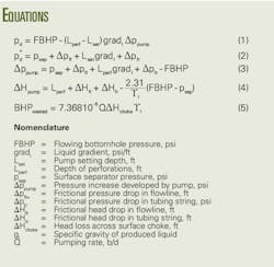
Based on the previous discussion, the pressure available at the ESP's discharge, as calculated from the well bottom upwards is found from Equation 1 (see equation box).
The performance curve of the tubing string represents the required discharge pressure of the ESP. It is calculated from the separator pressure and the pressure losses in the flowline plus the tubing string with Equation 2.
Because the available and the required pressures must be equal at the Solution Node, the simultaneous solution of the two formulas for the pressure increase to be developed by the ESP results in Equation 3.
Because the ESP industry uses head instead of pressure, one needs to divide the previous equation by the liquid gradient to arrive at the necessary pump head (Equation 4).
Equation 4, if evaluated over an appropriate range of liquid flow rates, represents the variation of the necessary head that the pump must develop to produce the different liquid rates from the given well. The head available from the ESP is, of course, described by its head-vs.-rate performance curve valid at a given frequency.
One finds the liquid rate developing in the total production system of the ESP installation at the intersection of the two curves where the required head equals the available head.
Choke effects
The calculation model previously discussed allows one to find the liquid rate developing in the ESP system and at the same time demonstrates the detrimental effects of production chokes on system performance.
As shown in Fig. 1, one can find the actual head necessary to produce the design rate from nodal calculations. This head, when well inflow performance is sufficiently accurate, represents the sum of all pressure losses in the well-ESP system and provides accurate information on the ESP system's deliverability.
The difference between the TDH value used during the original design and the calculated head gives the head drop that occurs across the choke. This head drop causes a large energy loss in the ESP system, and one can calculate the wasted energy (hp) with Equation 5.
In cases when the size of the production choke is relatively small with a large pressure drop across it, the system wastes large amounts of energy at the wellhead.
The ESP system's energy efficiency and profitability may deteriorate a lot as an effect of this condition. In extreme cases, only running a new, redesigned ESP unit in the well may solve the situation but at an increased cost.
The other possibility is the use of a variable speed drive (VSD) to change the driving frequency of the ESP motor. This entails the decrease of pump speed and as a consequent lowering of the head developed by the pump.
Changing the ESP's speed with a VSD changes the variation of all performance curves with the pumping rate. Based on manufacturer's published performance curves at a given electric frequency (usually 60 or 50 hz), the use of the Affinity Laws can determine the performance parameters (head, efficiency, and power requirement) at any other frequency.1
Use of these laws can lead to several preliminary conclusions for the case studied in this article when the original ESP unit operates at a reduced speed to decrease the pump's head, as follows:
• The head developed, power required, and efficiency of the same pump stage at the lower speed will decrease as compared with the original design,
• The loading of the motor and its efficiency will decrease,
• Due to reduced current requirement, electrical losses in the cable will be less.
The combined effect of these factors will cause changes in the total power requirement and in the power distribution of the ESP system. The following example problem illustrates the expected changes.
Example problem
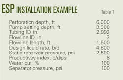
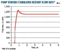
A 6,000-ft well (Table 1) has a design for producing 4,800 b/d of liquid with a 97-stage S5000N pump at 60 hz driven by a 200-hp electric motor. After installation of the equipment in the well, it produced more than its allowable (Fig. 4).
Nodal analysis with accurate well inflow data allowed for the calculation of the required head values, using Equation 4, for the possible range of production rates, as indicated by the dashed line.
As seen in Fig. 4, the system's stabilized rate, represented by Point 1, is at the intersection of the pump's head performance curve and the required head curve. Because this rate is too high, a production choke at the wellhead supplements the system's head requirement and shifts its operation to Point 2 at the desired rate of 4,800 b/d of liquid.
As seen from the pump performance curves at different driving frequencies, use of a VSD unit at a frequency of 51 hz eliminates the need of the production choke.
The following compares the use of the VSD unit with the original design at 60 hz operation.
The head drop across the choke is found as 1,843 ft (as read between Points 2 and 3) that causes, according to Equation 5, an energy waste of 65.2 hp. The pressure drop across the choke increases the wellhead pressure to 941 psi from the normal value of 143 psi, found from the separator pressure plus the pressure drop in the flowline.
Table 2 lists the ESP system's main parameters and compares the pump and motor performance data between the two cases.
As shown, the VSD unit decreases motor voltage to 1,849 v. where motor power decreases to 170 hp.
A comparison of the power conditions shows that the useful power of fluid lifting is identical and is calculated as 42.5 kw from the formula proposed by Lea et al.2
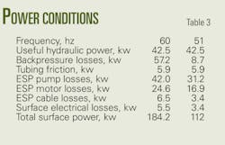
The accepted equations3 calculate the hydraulic and electrical losses in the different components of the ESP installation (Table 3).
As seen, the largest difference is in the amount of energy for overcoming the surface backpressure. The choked case requires 57.3 kw as compared with 8.7 kw for the 51 hz operation.
Energy losses in the pump and the motor, in spite of the lower individual efficiencies valid for 51 hz operation (Table 2), decrease because of the lower amount of power required to drive the pump against the lower total head.
Finally, the ESP system's surface power requirement has decreased to 112 kw from 184 kw for the case with a VSD operation. The almost 40% lower energy requirement clearly demonstrates the advantage of a VSD unit over the surface choke for controlling the production rate of ESP installations.
Fig. 5 compares the power distribution in the two cases and shows the relative magnitude of power losses in system components for each case. Here, again, the figure shows the large decreases in backpressure losses for the case without the surface choke.
The two system's overall energy efficiencies, for example the fractions of useful hydraulic power compared with the total power, are considerably different. The 51-hz operation with a 38% system efficiency is much better than the choked case with an only a 23% efficiency.
References
1. Takacs, G., Electrical Submersible Pumps Manual, Gulf Professional Publishing, An Imprint of Elsevier, 2009.
2. Lea, J.F., Rowlan, L., and McCoy, J, Artificial Lift Power Efficiency," 46th Annual Southwestern Petroleum Short Course, Lubbock, Texas, 1999.
3. Takacs, G., "Ways to Obtain Optimum Power Efficiency of Artificial Lift Installations," Paper No. SPE 126544, SPE Oil and Gas India Conference and Exhibition, Mumbai, Jan. 20-22, 2010.
The author
More Oil & Gas Journal Current Issue Articles
More Oil & Gas Journal Archives Issue Articles
View Oil and Gas Articles on PennEnergy.com
