Study examines options for limiting cold-weather pipeline flow reduction
Addressing increased crude oil viscosity at low temperatures in a transportation setting requires examining a variety of potential solutions, as simply preheating the oil or insulating the line is sometimes ineffective.
Problems related to crystallization and deposition of heavy organic fractions during production, transportation, and storage of crude oils can lead to considerable financial losses. Heavy organic fractions may include paraffins or waxes, resins, asphaltenes, and organometallic compounds present in crude oils in various quantities, states, and forms.1 Solid layers on the walls of pipelines increases pressure drop, increasing power requirements and often plugging pipelines.2
A number of investigators have researched the nature of heavy organics and mechanisms of organics deposition.3 Progress has occurred in the past several years in formulating accurate vapor-liquid phase behavior predictions of complex petroleum fluids,4 statistical mechanics of polydisperse polymer solutions, and kinetic theory of aggregation and precipitation.
Falling temperature during production of oil from wells affects deposition of heavy compounds in oil pipelines by increasing oil viscosity and flow pressure drop, making heat transfer from an oil pipeline to the environment an important design consideration.5-11
Limiting heat loss decreases oil viscosity and lowers pump horsepower requirements.12 Remery et al. mentioned that for long lines on which heat loss occurs through the wall of the pipe, keeping flow temperature above the critical wax and hydrate formation temperature requires remedial actions.5
Fields, facilities
The PA1 field lies 140 km northwest of Ahwaz in southern Iran, 21 km west of PA2 field and 35 km west of the CK anticline. The Iran-Iraq border divides PA1. An 8-in. OD, 26-km pipeline moves oil from PA1 to a CK production unit.
PA2 oil field is 110 km northwest of Ahwaz and around 35 km northwest of CK. Oil moves through an 8-in OD, 35-km pipeline from PA2 to CK.
DN oil field lies 30 km northwest of CK and 40 km east of DH field. DN measures 17 km long by 6-8 km wide. An 8-in. OD, 49-km pipeline transfers oil from DN to CK's production unit.
This article studies different possible solutions for crude cooling such as pipeline insulation, burying the pipeline, installing one or more preheaters in the ground surface, isolating the pipeline from the ground surface, and any combination of these to facilitate winter oil transfer from PA1, PA, and DN.
Fluid parameters
Fluids are Newtonian, non-Newtonian, pseudo plastic, and thixotropic, depending on the nature of their flow.13 Classification depends on fluid deformation caused by stress. Fluid behavior in a pipeline is a function of temperature, pressure, composition, and molecular interaction between components. Four groups of hydrocarbons affect oil flow: saturated hydrocarbons, aromatics, resins, and asphaltenes. These materials affect oil kinematic viscosity, directly affecting pipeline pressure drop.
Macro (alkanes) or micro (isoalkanes) crystal particles in either the α-phase or β-phase relating to wax materials in oil, causes serious problems in fluid flow through pipelines. Paraffin crystals in β-phase are triclinic, monoclinic, and orthorhombic and in α-phase are hexagonal. The molecular interaction of other materials in oil, like asphaltenes, resins, and paraffin materials, however, increases variation of petroleum fluid behavior.
Since petroleum fluids behave similarly to plastic substances, they are sometimes called pseudoplastics. Increasing the amount of paraffin, asphaltene, and resins in oil heightens oil's pseudoplastic behavior. These groups of materials form the wide spectrum of chained hydrocarbons or heavy rings which can be polymerized again and converted to heavier components. The spreading rate and size of these molecules in petroleum fluids is another important factor in determining fluid behavior of pipelines.
Fig. 1 shows the viscosity variation while transferring oil from PA2 field to CK production unit vs. pipeline flow temperature. Decreasing oil flow temperature from 130º F. to 77º F. increases oil viscosity and pipeline pressure drop by a factor of 19 and 115, respectively.
Equation 1 shows kinematic viscosity having a direct effect on pipeline pressure drop.
Equation 2, on the other hand, shows fluid kinematic viscosity as a function of temperature.14
Decreasing the ambient temperature around a pipeline increases the kinematic viscosity of oil fluid, leading to decreasing pressure and decreasing or blocking fluid flow.
Ambient parameters
Wind speed is one of the ambient effective parameters of oil flow rate and should be considered in lost energy calculations for pipeline flow. Increasing wind speed changes the heat transfer mechanism from free convection to forced convection, resulting in sharper decreases of pipeline temperature and oil flow rate. Equations 3 and 4 calculate lost energy for free convection and force convection heat transfer mechanisms, respectively.15
Calculating two cases of free and force convection heat transfer allows study of wind speed's effect on lost energy calculations of oil moving between PA1 and the CK production unit.
Calculations addressed the temperature difference of 30º F. between ambient and the pipeline surface (Equations 5-6) a wind speed of 15 mph with the same temperature difference (Equations 7-8).
Increasing the wind speed and changing the heat transfer mechanism increases lost energy by several times. The 15-mph wind speed increased lost energy by a factor of 24 compared with free convection.
Hydraulic study
Pipephase software calculated the pressure drop in an 8-in. OD pipeline between PA1 field and the CK production unit and investigated the effect of decreasing ambient temperature on oil flow rate.
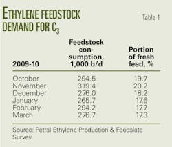
The program ran measured industrial data (Table 1) to check the accuracy of its simulation. Table 2 summarizes the results.
Acceptable convergence occurred between measured temperatures at the end of the pipeline and calculated values, but calculated pressures at this point do not agree with measured data. A flow efficiency correction factor matches the calculated values with industrial data. Table 2 and Fig. 2 show the correction factor as a function of ambient temperature.
Preheater installation
At low temperature oil viscosity increases rigorously, decreasing pipeline pressure and oil flow. Preventing reduction of oil temperature to a value lower than a specified temperature could decrease blocking, a subject considered by installing a preheater at the beginning of the PA1-CK pipeline.
Pipephase used the data in the box at the top of p. 57 to calculate the energy required by an H-1500 preheater to reach an oil flow rate of 2,000-7,000 b/d. Table 3 shows the results.
The optimum pipeline flow rate calculation used different values for beginning-line temperature and ambient temperature (Table 4). Transfering oil with a flow rate of 3,000 b/d, requires a beginning-line temperature of 120º F. for ambient temperature of 60º F.
Ambient temperature below 60º F. will decrease the oil flow rate and cause serious problems. A lone preheater at the beginning of the pipeline without any insulation can therefore not solve shipment problems.
Preheater, burying
In this case the pipeline's inlet temperature varies between 90º F. and 120º F. and the ground temperature for the buried pipeline equals 60º F. Burying the pipeline to 1.5-2 m and using the preheater increases flow by 5,000 b/d (Table 5). In this case, the optimum output temperature from the preheater is 90º F. Calculations also occurred for optimum oil flow rates of 100º F., 110º F., and 120º F.
Preheater, insulation
Combining a preheater and insulation on the PA1-CK pipeline calculated insulation heat transfer coefficient and optimum thickness of insulation for inlet oil flow conditions at 90-120º F. with ambient temperature 30-40º F. (Table 6).
For the worst conditions, an insulation thickness of 2 in. with a heat conductivity coefficient of 0.04 w/sq m-ºC. can produce 5,000 b/d. NIOC standard IPS-E-TF-700 classifies this insulation as Class A polyurethane with an optimum thickness of 50 mm. This insulation thickness operates as low as –12º C.
Table 7 shows the results of pressure drop calculations for oil moving through the PA1-CK pipeline using preheater and insulation. When pressure at the beginning of pipeline equals 400 psig, insulation with heat conductivity coefficients of 0.03-0.05 w/sq m-ºC. allows transfer of 5,000 b/d.
No preheater
Table 8 summarizes the results of simulating this scenario. The insulated pipeline without a preheater moves about 1,500 b/d. Table 9 summarizes the calculated results of a buried pipeline without a preheater. The flow rate is also roughly 1,500 b/d.
Hydraulic study
Table 10 summarizes the results of a trial run of field data gauging Pipephase's calculations. Flow efficiency correction factor enabled matching calculated pressure at the end of pipeline with field data. Table 11 provides simulation results, showing the correction factor to be a function of temperature (Fig. 3).
Preheater installation
Researches considered preheater installation at the beginning of the PA2-CK pipeline. Table 12 shows results of required energy calculations to maintain a flow rate of 2,000-5,000 b/d.
Calculating optimum pipeline flow rate required calculations for different values of beginning line temperature while varying ambient temperature between 40º and 90º F. Table 13 summarizes the results.
Transferring oil at 3,000 b/d requires the temperature at the beginning of line to reach 120º F. with an ambient temperature of 90º F. If the ambient temperature moves below 90º F. flow rate decreases, causing serious problems. A lone preheater at the beginning of pipeline therefore is not sufficient to move oil through the pipeline.
Preheater, burying
Pipephase software calculated the optimum flow rate for transferring through an 8-in. OD pipeline between PA2 field and CK production unit, fluctuating the temperature of oil flow at the pipeline entrance between 120° and 160º F. with a ground temperature of 60º F.
Table 14 shows burying the pipeline to a depth of 1.5-2 m and using a preheater boosts volumes by 600 b/d at an optimum preheater output temperature of 120º F.
Preheater, insulation
Investigating oil moving from PA2 to CK determined the preheater installation's effect when combined with insulation. Calculating the insulation's heat transfer coefficient and optimum thickness used an oil temperature at the pipeline entrance of 90º to 120º F. with an ambient temperature of 40º F.
Table 15 shows the results. The preheater and insulation in the form of ground surface are not sufficient to transfer oil through the pipeline.
Combination
Researchers also investigated insulating, burying, and installing a preheater at the beginning of the PA2 field pipeline. Table 16 shows this combination (burying the pipeline to a depth of 2 m) also failed to solve the problem of flow decreasing in pipeline, achieving a maximum flow rate of 1,000 b/d.
Multiple preheaters
Investigation also looked at several scenarios using more than one preheater and various combinations of surface, buried, and insulated or noninsulated pipelines. Tables 17 and 18 show the inefficiency in both surface and buried applications of using two preheaters without insulating the pipe. Installing two preheaters, one at the beginning of pipeline and another 18 km downstream, resulted in a maximum flow rate of 1,000 b/d.
The most problematic stretch of pipeline lies after the Tange Abougharib valley, which has a sharp elevation difference between its beginning and the production unit. Installing two preheaters and insulation allows the transfer of more than 5,000 b/d.
Table 19 shows the maximum distance between the second preheater and the production unit should be 22 km at an exit temperature of 120º F. or 25 km at an exit temperature of 130º F. Using 2-in. insulation for the first section and 1-in. insulation for the second section of the pipeline yields a heat conductivity coefficient of 0.03 w/sq m-ºC.
DN-DH pipeline
Table 20 shows the results of hydraulic study of oil transferring through the pipeline between the DN field and DH production unit. Shipment problems occur at flow rates greater than 6,000 b/d.
Table 21, however, shows that for the same flow rate in winter increasing the pipeline's pressure drop causes an intermittent flow regime (slug, elongated bubble) while decreasing the pressure drop in summer produces a stratified flow regime. Such oil transfer problems are not related to oil viscosity and are perhaps instead due to gas blocking phenomena. There is therefore no need to install a preheater and a separator on the DN manifold was suggested instead.
Separator installation
Table 22 shows the pressure-drop results of installing a separator in DN manifold. Increasing the oil flow rate leads to greater amounts of separated gas, with 85% of gas separated at 6,000 b/d.
Acknowledgment
This article was part of a research project sponsored by the National Iranian Oil Co. The authors thank Shiraz University for supporting this research.
References
1. Boukadi, A., Philp, R.P., and Thanh, N.X., "Characterization of paraffinic deposits in crude oil storage tanks using high temperature gas chromatography," Applied Geochemistry, Vol. 20, pp. 1,974-83, 2005.
2. Esmaeilzadeh, F., Fathi Kaljahi, J., and Ghanaei, E., "Investigation of different activity coefficient models in thermodynamic modeling of wax precipitation," Fluid Phase Equilibria, Vol. 248, pp. 7-18, 2006.
3. Branco, V.A.M., Mansoori, G.A., Xavier, L.C.A., Park, S.J., and Manafi, H., "Asphaltene flocculation and collapse from petroleum fluids," Journal of Petroleum Science and Engineering. Vol. 32, pp. 217-30, 2001.
4. Manafi, H., Mansoori, G.A., and Ghotbi, S., "Phase behavior prediction of petroleum fluids with minimum characterization data," Journal of Petroleum Science and Engineering, Vol. 22, pp. 67-93, 1999.
5. Remery, J., and Coutarel, A., "Pipeline Heat Loss in Rigid Flexible and Pipe-in-Pipe Deepwater Transport," Offshore. Vol. 61, No. 1, pp. 76-78, 2001.
6. Eliason, K.E., "Method of Insulating a Pipeline," United States Patent, No. 3,774,281, 1973.
7. Mi, B., and Wypych, P.W., "Pressure Drop Prediction in Low-Velocity Pneumatic Conveying," Power Technology, Vol. 81, No. 2, pp. 125-37, 1994.
8. Newberry, M.E., "Chemical Effects on Crude Oil Pipeline Pressure Problems," Journal of Petroleum Technology, Vol. 36, No. 5, pp. 779-86, 1984.
9. Kaushal, D.R., and Tomita, Y., "An Improved Method for Predicting Pressure Drop along Slurry Pipeline," Particulate Science and Technology, Vol. 20, No. 4, pp. 305-24, 2002.
10. Groch, S.W., and Jarvis, H.F., "Method of Thermally Insulating Pipe," United States Patent, No. 3,979,818, 1976.
11. Sumner, G.R., "Offshore Pipeline with Waterproof Thermal Insulation," United States Patent, No. 5, 871,034, 1999.
12. Turner, J.B., "Pipeline Forced Air Convective Heat Transfer System," United States Patent, No. 3,815,671, 1974.
13. Streeter, V.L., Wylie, E.B., and Bedford, K.W., "Fluid Mechanics," 9th edition, WBC/McGraw-Hill, New York, NY, 2002.
14. Poling, B.E., Prausnitz, J.M., and O'Connell, J.P., "The Properties of Gases and Liquids," 5th edition, McGraw-Hill, New York, NY, 2001.
15. Holman, J.P., "Heat Transfer," 8th edition, McGraw-Hill, New York, NY, 1997.
The authors
More Oil & Gas Journal Current Issue Articles
More Oil & Gas Journal Archives Issue Articles
View Oil and Gas Articles on PennEnergy.com
