Study examines coating compatibility with CP
For a pipeline coating to be truly compatible with cathodic protection (CP), the coating should allow CP protection to the pipe even if disbondment occurs and water penetrates between the coating and pipe. CP must be adequate to provide the needed current to significantly reduce or eliminate the corrosion under the nonshielding disbonded coating.
Coatings that shield CP when there is a disbondment are a major cause of external corrosion problems on pipelines. Even with proper application some coatings can disbond through soil stress and other methods.
Background
When applying CP to coated pipelines, end users must consider the problems faced if the coating disbonds. CP current is very effective when it has a path to the pipe metal. Disbonded coatings shielding CP, not lack of CP itself, cause most external corrosion on pipelines.
When disbondment or blistering occurs most coatings divert current from its intended path, preventing CP current from adequately protecting the external surfaces of a pipe. A coating must conduct CP current even when disbondment occurs to adequately protect underground pipelines.1 Certain pipeline coatings will allow CP current to protect the pipe if disbondment occurs and water penetrates between the coating and the pipe.
This article discusses the differences between the two types of coating systems and how CP works with each.
Cathodic protection
The electrochemical process of cathodic protection causes the environment around the cathode (pipe, tank, etc.) to become alkaline, especially at the surface of the metal being protected. The pH of typical pipeline surfaces with adequate CP should be 9-13. This range protects steel and reduces or eliminates corrosion.
Cathodic disbondment (CD) testing, whether long or short-term, shows how well the adhesion of the coating will withstand the electrochemical process of cathodic protection. Coatings need to withstand the alkaline environment as well as hydrogen evolution and other potentially damaging electrochemical changes, making successful CD testing a requirement for pipeline coatings used in conjunction with CP.
Every coating system has finite life and eventually degrades, allowing oxygen, water, and chemicals to reach the substrate.2 Increased CP often appears to be the best or only solution to prevent corrosion on a pipeline with poor or disbonded coatings. Increasing CP may help meet certain criteria and protect pipe exposed to electrolyte, but it does not always protect the pipe under disbonded coatings, allowing corrosion to continue unless the coatings are replaced.
Increasing CP creates other problems, including the possibility of further disbondment and coating deterioration, as well as adding potential interference to other systems and increasing costs.
Coating failure
Each coating manufacturer attempts to make coatings that will not fail. Poor surface preparation, application technique, soil stress, or selection of the wrong coating for the environment cause most failures. All coatings, however, experience disbondment, making behavior of a disbonded coating important in the overall performance of a coating system.3 4
Acidic and near neutral pH environments developed under disbonded shielding pipeline coatings can lead to corrosion and possibly environmentally assisted cracking. As the coating deteriorates, however, and its permeability to O2 increases, the corrosion rate deep in the crevice (or blister) could become substantial given CP shielding.5
Any changes in the properties of a coating constitute a coating failure.6 Soil stress and other mechanical damage can also create disbondment problems affecting pipeline coatings. Damage may lead to pipeline corrosion failure and costly repair (OGJ, Aug. 26, 1985, p. 63). Some coatings are more subject to this problem than others.
All coatings have varying dielectric properties reducing the tendency of the electrolyte to complete the electrical circuit between the adjacent anodic and cathodic sites on a substrate, thereby mitigating corrosion.2 The worst case coating failure prevents both the coating and the CP from protecting the pipeline.6 Failure to understand coating’s influence, especially on the CP system, has caused many premature pipeline failures.7
Many pipelines use fusion-bonded epoxy (FBE) coating. Running internal line inspection (ILI) tools in FBE coated pipelines rarely finds external corrosion, except at girth welds coated with a different coating that shields CP if the coating fails. FBE is a permeable coating and despite a high coating resistance current could pass directly through the FBE barrier to the underlying steel, developing a high pH environment in disbondment.8
ILI tools have shown corrosion under many types of non-FBE girth weld coatings after only a few years in service.
CP compatibility
Carefully selecting field-applied (girth weld and rehabilitation) coatings ensures their compatibility with CP should a coating failure or disbondment occur. Companies have performed expensive rehabilitations only to find their choice of coating material eventually disbonded, allowing further corrosion at additional expense. Certain coatings allow CP current to protect the pipe should the coating disbond, reducing or eliminating corrosion. These coatings are compatible with CP.
Field testing is the most effective way to determine a coating’s CP compatibility. CP changes the pH of the electrolyte at the pipe surface to an alkaline pH, making pH testing an excellent way to determine the effectiveness of the CP under disbonded coating.
Laboratory tests can also establish a coating’s effectiveness in allowing CP to protect the pipe under a disbondment. Testing whether a coating is truly compatible with CP requires a properly designed test apparatus.9
Articles written about testing to determine what happens under most disbonded coatings conclude it is difficult to achieve protection past the local holiday, much less under coatings without holidays in the disbonded area.3 10 11
Not all coating failures result in corrosion. Some coating failures have little or no effect on the corrosion rate of the pipe, including FBE.
External corrosion rarely occurs on pipelines coated with FBE if adequate cathodic protection is available. Pipe will remain protected and blistering and coating disbondment of FBE coatings will not present an integrity threat to a pipeline.12
Laboratory and field testing has also proven at least one geotextile mesh backed tape coating has this characteristic when adequate CP is available. These coating systems may not necessarily maintain protection in all conditions, but field and laboratory results have proven a tendency to mitigate corrosion even under disbonded coating.
FBE has experienced numerous failures over roughly 40 years, but these have very rarely led to corrosion or stress corrosion cracking (SCC). Low enough electrical resistance will allow cathodic protection to prevent corrosion on a pipe with disbonded or blistering coating since FBE is nonshielding.13 Adequate CP reduces or eliminates corrosion, including SCC, if water penetrates under the coating. When CP-compatible coatings degrade or ground water contacts the pipe, the surface remains protected from corrosion and SCC because the CP current can pass through the permeable coating.14
Other structures, however, can sometimes cause shielding, or interference from foreign DC or AC sources can cause corrosion not controlled by the pipeline CP or coating systems.
The documents referenced in this article include case histories and information about pipeline coatings that shield CP when disbondment occurs, allowing external corrosion. The references also discuss coatings that allow enough CP to reduce or eliminate corrosion on the structure even if the coating system adhesion fails and water penetrates between the coating and the pipe.
Case histories
Case histories of some coatings that are compatible with CP and some that are not follow.
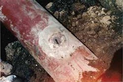
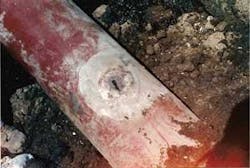
• Case History 1. Though rare, external corrosion has been found on FBE coated pipelines. An ILI tool run in 1992 found a pit at the 12:00 o’clock position on this line (Fig. 1).
Excavation removed a 1-2 ton boulder from the top of the pipe, revealing several blisters in the FBE coating. The 12:00 o’clock pit was directly under the boulder, which had evidently shielded CP from the pipe. No corrosion was found under any of the other blistered FBE, reinforcing its typical nonshielding properties.
The damaged pipe was 12-in. OD coated with 22 mils of FBE and entered service in the early 1980s, operating at about 180° F. The “On” potential was –1,160 mv (cse) and the CP criterion used on this pipeline was an “ON” of –850 mv..
A large waste management pond also lay just above the pipeline and there were bacteria in the water around the pipe. Heat caused the failure of a variety of other coating systems used on pipelines in the area (extruded polyethylene, solid film-backed tapes, and coal tars), allowing water into the space between the solid film coatings, shielding the CP, and allowing corrosion.
• Case History 2; FBE-coated 16-in. OD diameter pipe laid in 1985 and internally inspected in 1999. The ILI run showed only internal corrosion, validating use of the FBE coating which remained in excellent condition. One area exposed for verification had blistering, but no external corrosion.
• Case History 3; FBE-coated 42-in. nominal pipe-size pipe examined after 8 years of service at ambient temperature. Excavation revealed several blisters. Blisters included:
- —Medium-to-large with no holidays and bright steel under the coating.
- —Medium-to-large with darkened steel.
- —Small with liquid under the coating.
The excavated pipe was exposed to the atmosphere for an extended period before the coating was evaluated, perhaps allowing evaporation or runoff of the water under the large blisters.
Deionized water used to wash the surfaces under the larger blisters allowed analysis. Water from the blisters with darkened metal showed about three times the amount of sodium, with some chloride and sulfate, as blisters with bright steel. The pH of water under the small blisters was slightly >13, but still within the range of typical continued CP protection.
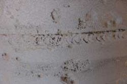
• Case History 4. Geotextile mesh backed coating has rarely failed. One pipe coated with this and excavated after 3 years of service showed minor wrinkling and water between the coating and pipe. Application occurred in a severe soil stress area without proper tension, without outer wrap, without stripping of the weld seams, incomplete primer application, and over a disbonded coal tar allowing water to migrate along the weld seam under the mesh-backed tape coating.
There was, however, no significant corrosion or metal loss. The pH of the water under the coating was 10, showing the coating’s compatibility with CP even with disbondment and water penetration (Fig. 2).
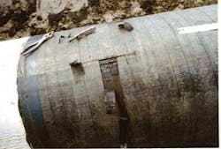
• Case History 5. Several coatings applied to an excavated area on a 30-in. OD natural gas pipeline allowed for testing with geotextile mesh backed tape. The sunny side of the pipe was dry, but the shady side had condensation. Testers intentionally coated the pipe while partially wet to evaluate the coating’s performance, reexcavating the site after 3 years of service.
As expected, the coating did not bond to the wet surface, but was well bonded to the dry side of the pipe. The wet area, however, had a pH of 11 under the pipeline coating, showing continued CP even with adhesion loss and water penetration (Fig. 3).
• Case History 6; shrink sleeves applied to a 10-in. OD pipe as girth weld coating. FBE coated the main body of the pipe. An ILI run 9 years later only found corrosion at the girth welds under shrink sleeves wrinkled from soil stress and possible poor application. Corrosion under some sleeves required exposing the pipe and replacing the coating.
• Case History 7; solid film-backed tape coating used on girth welds of a 20-in. OD pipeline installed in 1980. A 1999 ILI tool run exposed many areas of corrosion under the tape coating on girth welds and other areas.
• Case History 8; 6-in. OD insulated pipeline installed in 1979 with a polyethylene (PE) tape anticorrosion barrier, roughly 1 in. of foam, and a PE-tape outer jacket. Poorly applied field joint coatings caused severe external corrosion at girth welds, making the pipeline unable to withstand axial and bending stress during excavation which caused the weld to crack. The line was not leaking prior to the dig.
• Case History 9; 6-in. OD, 27 km thermally insulated pipeline constructed in 1989. Coating consisted of an FBE anticorrosion barrier, 2 in. of foam, and an extruded PE outer jacket. Joint coatings included FBE, injection molded foam, and a shrink sleeve outer jacket. A pipeline inspection in 2005 discovered 209 anomalies only 3 of which were due to external corrosion.
All external anomalies measured <30% WT and were in the body of the pipe, not near the girth welds. External indications were not exposed and may have been steel defects and not corrosion.
References
- Beavers, J.A., and Thompson, N.G., “Corrosion Beneath Disbonded Pipeline Coatings,” Materials Performance, p. 19, April 1997.
- “Coatings Used in Conjunction with Cathodic Protection,” NACE International Technical Committee Report Item No. 24207, p. 2, 2005.
- Beavers, J.A., and Thompson, N.G., “Corrosion Beneath Disbonded Pipeline Coatings,” Materials Performance, p. 13, April 1997.
- Moore, D.P., “Cathodic Shielding Can be a Major Problem After A Coating Fails,” Materials Performance, p. 44, April 2000.
- Song, F.M., Kirk, D.W., Cormack, D.E., and Wong, D., “Barrier Properties of Two Field Pipeline Coatings,” Material Performance, p. 26, April 2005.
- Papavinasam, S., Attard, M., and Revie, R.W., “External Polymeric Pipeline Coating Failure Modes,” Materials Performance, p. 28, October 2006.
- Mills, G., “The Pipe Coating as an Engineered Part of the Cathodic Protection System,” Materials Performance, p. 13, December 1988.
- Been, J., Given, R., Ikeda-Cameron, K., and Worthingham, R., “Investigating Coating Performance,” Pipeline and Gas Technology, p. 36, April 2007.
- Norsworthy, R., “Fail Safe Tape System Used in Conjunction with Cathodic Protection,” Materials Performance, p. 35, June 2004.
- King, F., Jack, T., Kolar, M., and Worthingham, R., “A Permeable Coating Model for Predicting the Environment at the Pipe Surface Under CP-Compatible Coatings,” NACE Corrosion 2004, Orlando, Mar. 21-26, 2004.
- Ruschau, G.R., and Chen, Y., “Determining the CP Shielding Behavior of Pipeline Coatings in the Laboratory,” NACE Corrosion 2006, San Diego, Mar. 12-16, 2006.
- Been, J., Given, R., Ikeda-Cameron, K., and Worthingham, R., “Investigating Coating Performance,” Pipeline and Gas Technology, p. 41, April 2007.
- Kehr, J.A., “Fusion Bonded Epoxy (FBE)—A Foundation for Pipeline Corrosion Protection,” NACE Press, p. 471.
- King, F., Jack, T., Kolar, M., and Worthingham, R., “A Permeable Coating Model for Predicting the Environment at the Pipe Surface Under CP-Compatible Coatings,” NACE Corrosion 2004, Orlando, Mar. 21-26, 2004.
The author
Richard Norsworthy ([email protected]) is director of Lone Star Corrosion Services for Polyguard Products. Prior to this, his work included 10 years as a consultant and time at both Mobil Pipeline and Amoco Pipeline as a corrosion specialist. Norsworthy earned a BS in mathematics (1968). He is a member of several NACE technical committees and a trustee of the North Texas DFW section.


