Special Report: LIQUIDS ENTRAINMENT–1: Changing operating conditions lead to compressor damage
This is the first of three articles that describe BP’s experience with reciprocating compressor damage from liquids intrusion at two facilities, in Oklahoma and Alaska. Due to the different damage mechanisms, facility constraints, underlying causes, and site-specific factors, the specific actions required were quite different for each installation.
Operators of reciprocating compressors are generally aware of the danger to their equipment from ingestion of liquids. At a basic level, the solution is simple: Provide compressors with a clean, dry suction stream.
The GPSA Data Book provides this summary: “Reciprocating compressors should be supplied with clean gas as they cannot satisfactorily handle liquids and solid particles that may be entrained in the gas. Liquids and solid particles tend to destroy cylinder lubrication and cause excessive wear. Liquids are noncompressible and their presence could rupture the compressor cylinder or cause other major damage.”1
In reality, however, that damage to reciprocating compressors from liquids ingestion is not uncommon reliably indicates the difficulty operators often face in providing clean, dry gas to their units.
BP owns and operates the Milne Point oil production facility on Alaska’s North Slope where processing facilities are enclosed in heated, adjoining modules. The gas compression module houses two 3,450-hp reciprocating compressors.
Over time, the frequency and severity of compressor component failures have increased. Intense examination identified both mechanical and process-related causes for the failures, including entrainment of water and NGLs in the compressor suction. Damage caused or exacerbated by ingested liquids included bearing failures, damaged cylinder lining, sheared wrist pins, sheared cylinder attachment bolts, and cracked pistons.
A separate liquid slugging incident at an Oklahoma compressor station resulted in three damaged pistons on two out of six 1,000-hp reciprocating compressors. In this case, the problem was solved with additional pipeline pigging capability and new, more reliable vertical inlet separators.
At Milne Point, poor separation performance of existing suction scrubbers was predicted by computational fluid dynamics (CFD) modeling and confirmed by laser isokinetic probe sampling to quantify liquid entrainment. Analysis of operating data also indicated condensation of liquids in suction piping downstream of the scrubbers.
A multifaceted solution was required, including:
- Reconfiguration of suction cooler temperature control logic.
- Upgrades to suction scrubber level control, alarm, and shutdown systems.
- Installation of in-line, axial flow cyclonic demisters immediately upstream of compressor suction bottles.
- Heat tracing and insulation of piping and suction pulsation bottles downstream of the new demisters.
Other options were considered but rejected for various reasons.
This three-part series will discuss several noteworthy aspects of these two repairs, including the role of changing operating conditions in leading to compressor damage (Part 1), the validation of CFD modeling by on line laser isokinetic probe sampling for liquid entrainment and impact of NGL solubility in compressor lube oil (Part 2, May 25, 2009), and use of state-of-the-art in-line cyclonic separation technology to mitigate liquid entrainment (Conclusion, June 8, 2009).
Oklahoma incident
In late 2006, a field compression facility in Oklahoma lost two reciprocating compressors when well fluids, primarily produced water, flowed past the inlet separator and the compressor scrubber and into the compressor cylinders.
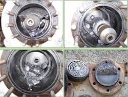
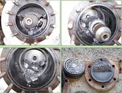
The incident damaged two pistons from the first stages of one machine and one piston from a second machine. Fig. 1 shows some of this damage. The resulting failures would have resulted in significant downtime if the facility had not planned for spare compression.
The processing facility contains six reciprocating compressors that boost wellhead pressures to a delivery pressure of nearly 900 psig from suction of 60 psig. After compression, the gas undergoes sweetening and dehydration before entering a third-party pipeline as sales gas.
These compressors are Ariel frame 4 (JGK) with Caterpillar drivers (Model 3516 3RC) rated for 1,000 hp. The facility has the luxury of spare compression, which was of great benefit in minimizing the cost of this incident.
The facility had been in service for several years. With time, produced fluids from the wells have increased, both from additional wells coming on production as well as from aging wells now producing more water.
Several times before the incident, the inlet separation equipment was overwhelmed with produced fluids slugging into the facility. The compressor shutdown devices were able to protect the machine by shutting down the compressors.
During a heavy liquid slugging incident in 2006, however, the well fluids overwhelmed the inlet separators, and the compressor safety devices did not react quickly enough to shut down the machines. The liquids entered the cylinders and damaged three pistons in two machines.
Interestingly, during hazardous operations (HAZOP) and layer of protection analyses (LOPA) review of this facility a month before the incident, the engineering and operation team identified this scenario as highly likely with compressor damage a result. The team recommended that either additional fluid separation be installed to collect produced fluids entering the facility or that additional faster-acting shutdown devices that were LOPA rated be installed to prevent the incident.
Before the final LOPA analysis and LOPA verification were completed, the incident occurred. The final LOPA report recommended immediate action to prevent reoccurrence. Engineering accelerated the program to add additional separation.
As a result of this incident, engineering installed new vertical inlet separators at both compressor stations designed with high-level switches that would shut down the compressors and prevent reoccurrence.
The switches were LOPA classified, were tagged as safety-critical equipment, and would undergo function testing outlined according to LOPA requirements. Additionally, operations also added pipeline pigging capability in the gathering system to reduce the volume of slugs entering the facility.
These modifications have reduced the cost for compressor valve repairs. After the 2006 incident and subsequent installation of new separators and liquid-level switches, the compression station has experienced no more problems related to liquids in the compressor cylinders.
North Slope repair, upgrade
The self-contained Milne Point oil production facility on Alaska’s North Slope, 30 miles west of giant Prudhoe Bay field includes power generation and all processing equipment necessary to produce, treat, and deliver more than 30,000 b/d of sales oil to the Trans-Alaska Pipeline.
To prevent melting the North Slope permafrost, all process facilities are housed in elevated, adjoining modules. All compressors and associated scrubbers and coolers are in a single module.
Unlike Prudhoe Bay facilities, which use centrifugal compressors to handle much higher gas volumes, most of Milne Point’s compression needs are met by two parallel low-speed reciprocating compressor trains (A and B trains). Each train includes two large compressors (Big A and Big B) for bulk compression and two small compressors (Little A and Little B) for handling low-pressure secondary and tertiary production-separator vapor and high-pressure injection gas.
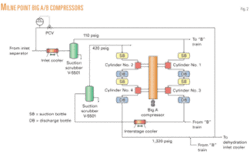
The remainder of this discussion will focus entirely on the Big A/B compressors (Fig. 2).
Each of the Big A/B compressors is a 327 rpm, four-throw Clark CLRA compressor driven by a 3,450-hp electric motor. Each unit compresses 18 MMscfd of produced gas to 1,320 psig from 110 psig inlet pressure for delivery to field gas lift and gas injection systems.
During normal operation, both compressors are running, with no spare capacity. Suction scrubbers and coolers are common to both compressors. Fig. 2 provides a simplified process flow diagram of the Big A/B compression system; only the Big A unit is shown, but the Big B unit has an identical configuration.
History
The Milne Point facility began operation in 1985; BP acquired it in 1994. The following year saw completion of a major plant expansion to increase fluid-handling capacity. The Big A/B compressors were recylindered to increase maximum gas capacity to 45 MMscfd from 32 MMscfd, but no corresponding changes were made to the compression train’s piping.
The two original suction scrubbers, V-5501 and V-5511, were not replaced, but their original vane packs were, with higher capacity vane pack assemblies. The new vane pack units were equipped with mesh pads on the inlet side to improve flow distribution into the vanes.
Compressor maintenance records show that since the 1995 expansion, the Big A/B compressors have experienced increased mechanical failures and required more frequent maintenance.
Within the last few years, the failure rate has accelerated, with more serious damage including two Big A cracked pistons on cylinder No. 3, damaged cylinder linings, and a sheared wrist pin on each compressor. Main and connecting rod bearings have failed within a few weeks to months of installation (Fig. 3).
In February 2007, Big A experienced multiple mechanical failures, including main bearing failure, sheared cylinder attachment studs, and a bent crankshaft. A complete rebuild of this machine was necessary. Fig. 4 illustrates the impact of this major repair on total compressor throughput.
Initial attempts to resolve the increasing compressor problems focused on reducing excessive vibration caused by lack of adequate compressor support. Most low-speed reciprocating compressors are mounted on massive concrete bases to prevent compressor movement by absorbing shaking forces inherent in reciprocating compressors.
Big A/B compressors, however, are secured to the base of an elevated steel module with no underlying concrete mass to dampen vibration. These early efforts were only partially successful, often resulting in shifting vibration and shaking forces from one part of the compressor module to another.
In response to the rapidly deteriorating mechanical integrity of these machines, BP initiated a project in early 2006 to design new compressors to replace Big A/B. Concurrent with the compressor replacement project began an intensive effort to determine whether the existing machines could be adequately repaired and upgraded to allow for safe, long-term operation.
This effort concluded that the main driving forces responsible for the excessive mechanical failures were subframe flexibility (of the steel module), inherent compressor weight imbalance, and liquids ingestion. Specific recommendations were made to correct each of these underlying causes to allow for safe, reliable operation of Big A/B for several more years.
Most have now been implemented, with positive results. The last major recommendation to be implemented is installation of four in-line axial-flow cyclonic demisters, one upstream of each Big A/B compressor suction bottle on the Nos. 1 and 2 cylinders. These units are currently scheduled to be installed this summer during the Milne Point turnaround.
Unlike the Oklahoma incident, in which compressor pistons were destroyed by a single known liquid slugging event, no absolute cause and effect relationship between liquids ingestion and compressor damage could be established for the Milne Point machines. But liquids were determined to be a significant factor contributing to much of the damage that has occurred in the past.
Even after completion of the Big A rebuild in April 2007, connecting-rod bearing have continued to fail at an abnormally high frequency. Until the demisters are installed, there will continue to be loss of lubrication due to persistent ingestion of entrained NGLs.
Evidence of entrainment
After Big A sustained major damage in February 2007, the only viable option to restore compressor capacity in the short term was to rebuild this machine completely. A new compressor could not have been operational for at least 18 months.
Visual detection
Beginning in late February 2007, Big A was disassembled and rebuilt over the next 10 weeks. When Big A was opened, liquids were found in the suction bottles, discharge bottles, and distance pieces. For the Nos. 1 and 2 cylinders, the liquids found in the suction bottles and distance pieces were clear to amber colored. These liquids had the smell and appearance of natural gas condensate.
Later analysis confirmed them to be a mixture of water and NGL, typical of suction-scrubber liquid dropout. Liquids found in the discharge bottles of Nos. 1 and 2 cylinders and the distance pieces and suction bottles of the Nos. 3 and 4 cylinders appeared very thin lube oil. Lab analysis confirmed that these liquids were lube oil diluted with NGL.
Knock-sensor indications
In 2006, each of the Big A/B cylinders was equipped with knock sensors to monitor the relative magnitude of forces generated within each cylinder. These sensors were initially monitored to detect impending mechanical damage. More information about the presence of entrained liquids, however, revealed a correlation between liquids ingestion and knock-sensor indications.
In particular, whenever changes in operating conditions caused a significant increase in the rate of liquid dropout in the suction scrubbers, operators noticed elevated cylinder knocking. This generally continued until the scrubber liquid formation returned to normal.
Elevated knock-sensor activity also occurred immediately after a large manual increase of the discharge temperature set points for the gas coolers upstream of the suction scrubbers. This was later determined to result from increased condensation of liquids downstream of the scrubbers as warmer, richer gas came into contact with cooler suction piping and pulsation bottles.
Suction bottle drains
After discovering liquids in the suction and discharge bottles of Big A, operators installed manual drain lines on all pulsation bottles on Big A and Big B, with the exception of the Nos. 3 and 4 cylinder discharge bottles. These drain lines were plumbed to the closed hydrocarbon drain system but equipped with connections for collecting samples of the liquids drained from each bottle.
During the Big A rebuild, operators drained liquids daily from the Big B suction bottles to quantify volumes and verify appearance of the drained liquids. They repeated this experiment in November 2007 with both Big A and Big B operating. In all instances, the liquids drained from the Nos. 1 and 2 bottles were clear and smelled like gasoline. Likewise, all liquids drained from the Nos. 3 and 4 bottles appeared as thin lube oil.
These visual results were consistent with earlier observations of liquids discovered during the Big A teardown. The table shows the average daily volumes of liquids drained from each suction bottle during the April and November tests.
A notable aspect of these results is the larger quantity of liquids drained from Big A than from Big B. The compressors are virtually identical and the main suction line from each suction scrubber tees into the compressor suction header right in the middle, at an equal distance from each Nos. 1 and 2 suction bottle. Piping geometry directly upstream of this tee is presumed to be the cause of the preferential flow to the A machine.
This difference in liquid volumes is entirely consistent with both operating data and historical mechanical failure records. Bearing failures and cylinder knocking related to liquids ingestion are more frequent and severe on Big A than on Big B.
Also, both of the No. 3 piston failures occurred on Big A. These failures were most likely related to liquids ingestion, as described in the next article in this series.
Reference
- GPSA Engineering Data Book, 12th Edition, Tulsa: Gas Processors Suppliers Association, 2004.
The authors
Paul Tenison ([email protected]) is a facility engineer at BP Alaska’s Lisburne production center on the North Slope. Previously, he worked in Anchorage as a senior process engineer assigned to several projects, including the Milne Point Compressor upgrade and repair project. His career in process and facility engineering began in 1979 with ARCO Oil & Gas Co., Dallas. He has worked in Bakersfield, Calif., Denver, and for the last 21 years in Alaska. Tenison graduated from Oklahoma State University in 1979 with bachelor and master degrees in chemical engineering.
Ralph Eguren ([email protected]) is a process engineering advisor with BP America Ltd., North America Strategic Performance Unit in Houston. He has worked in the E&P industry for 31 years as a researcher (in Amoco Production Co. research center), later as technical consultant for Amoco in its worldwide engineering organization. In 2000, he joined BP as a result of a merger with Amoco. Eguren holds a BS in chemistry from Southern Nazarene University (Oklahoma) and BSChE and MSChE from the University of Tulsa. He is member of AIChE, SPE, and NACE and on the planning committee for the annual Laurence Reid Gas Conditioning Conference and BP’s industry representative to Amine Best Practices Group (ABPG).


